7-10
Power unit assembly
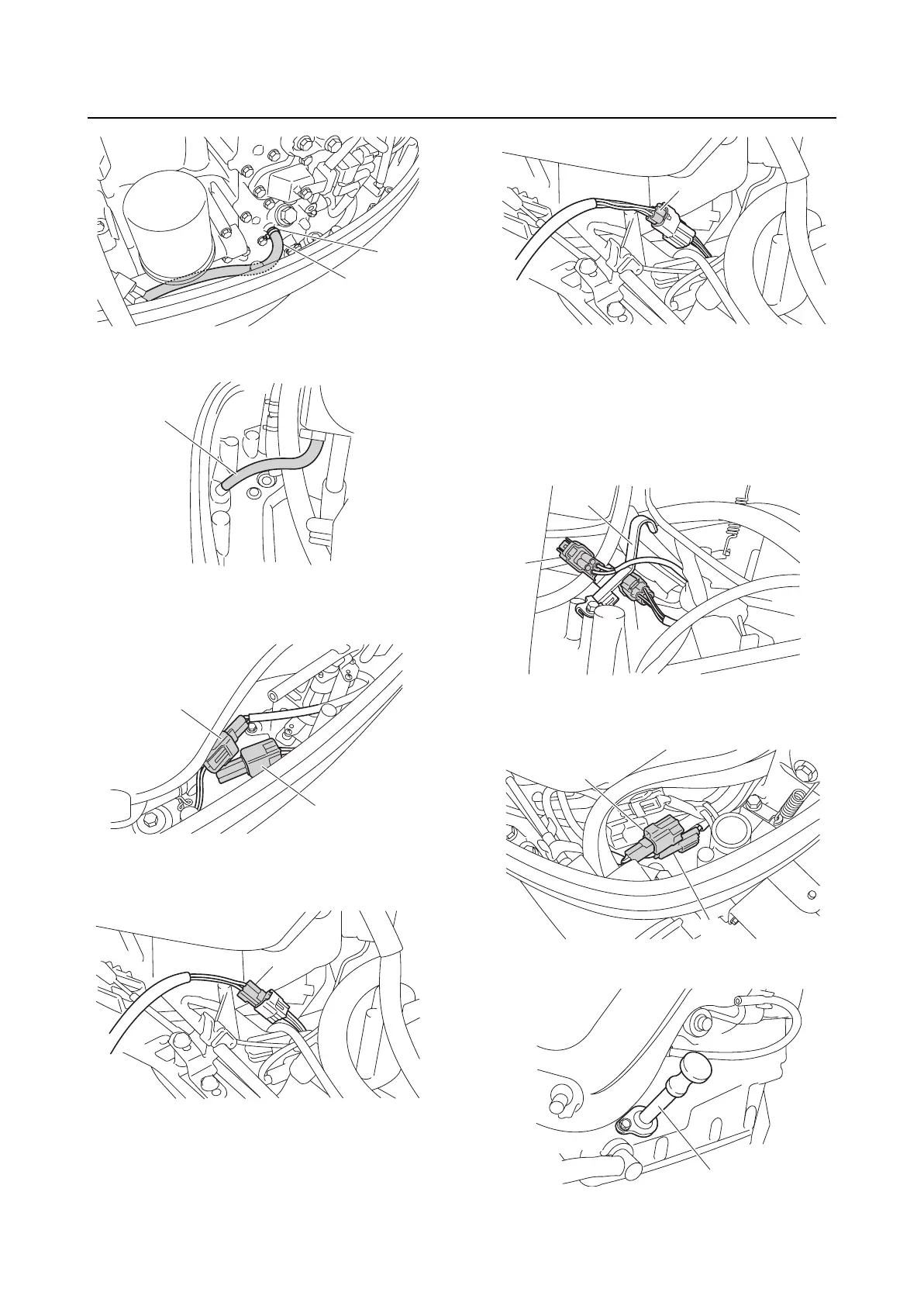
5. Connect the cooling water pilot hose “1”.
6. Connect the shift cut-off switch coupler
“a” and shift position switch coupler “b”.
7. Connect the 6Y8 Multifunction Meter har-
ness coupler “a” or gauge coupler “b”.
A. 6Y8 Multifunction Meter
B. Conventional gauge harness
8. Install the 6Y8 Multifunction Meter har-
ness coupler “a” and gauge harness cou-
pler “b” to the bracket “1”.
9. Connect the PTT switch coupler “a” and
trim sensor coupler “b”.
10. Install the dipstick guide “1”.
1
2
1
a
b
a
A
b
B
1
b
a
a
b
1

 Loading...