9-59
PTT gear pump
Assembling the gear pump
Lubricate the parts using ATF Dexron II dur-
ing assembly.
When assembling the PTT unit, do not use
a rag. Otherwise, dust and particles could
get on the PTT unit components, causing
poor performance.
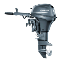
1. Install a new O-ring “1” and the valve
seat “2”.
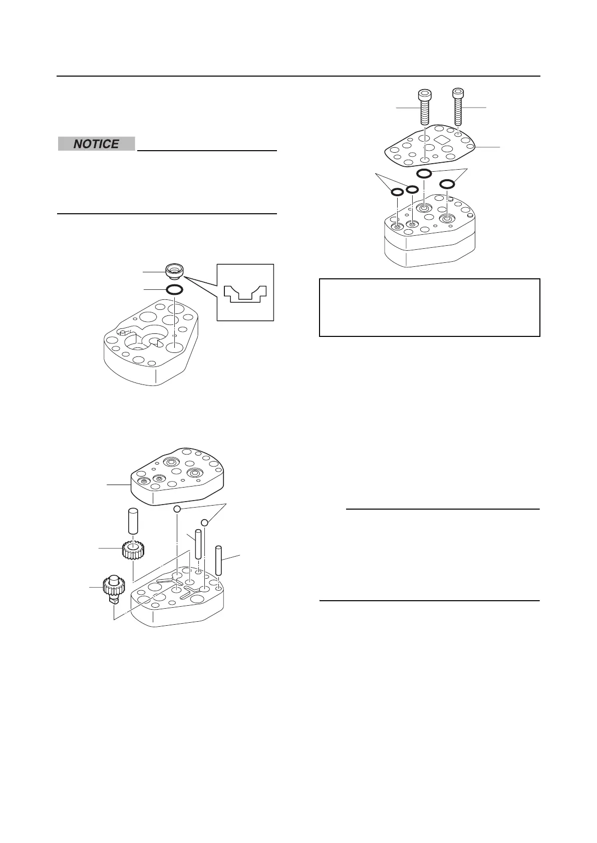
2. Install the drive gear “1”, driven gear “2”,
balls “3”, and pins “4”, and then install the
gear housing “5”.
3. Install new O-rings “1” and “2” and the
bracket “3”, and then tighten the pump
bracket bolts “4” and “5” to the specified
torque.
4. Install a new valve seal “1”, the valve pin
“2”, and the spring “3”, and then install
the valve lock screw “4”.
5. Install a new O-ring “5” to the valve sup-
port pin “6”.
6. Install the ball “7”, valve support pin “6”,
and spring “8”, and then install the valve
lock screw “9”.
TIP:
• Install the valve lock screw “4” and valve
lock screw “9” to the height “a” and depth
“b” that were measured before removing
them.
• If installing new parts, install them accord-
ing to the preceding reference data.
2
1
5
1
2
3
4
4
Pump bracket bolt (M5) “4”:
7 N·m (0.7 kgf·m, 5.2 ft·lb)
Pump bracket bolt (M4) “5”:
4 N·m (0.4 kgf·m,, 3.0 ft·lb)
1
2
3
45

 Loading...