9-18
Upper case
0
1
2
3
4
5
6
7
8
9
10
A
Disassembling the upper case
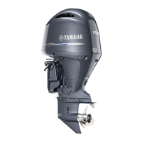
1. Remove the drain bolt “1”.
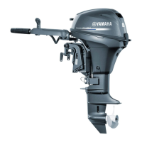
2. Remove the upper case bolts “1” and “2”,
and then remove the oil pan assembly
“3”.
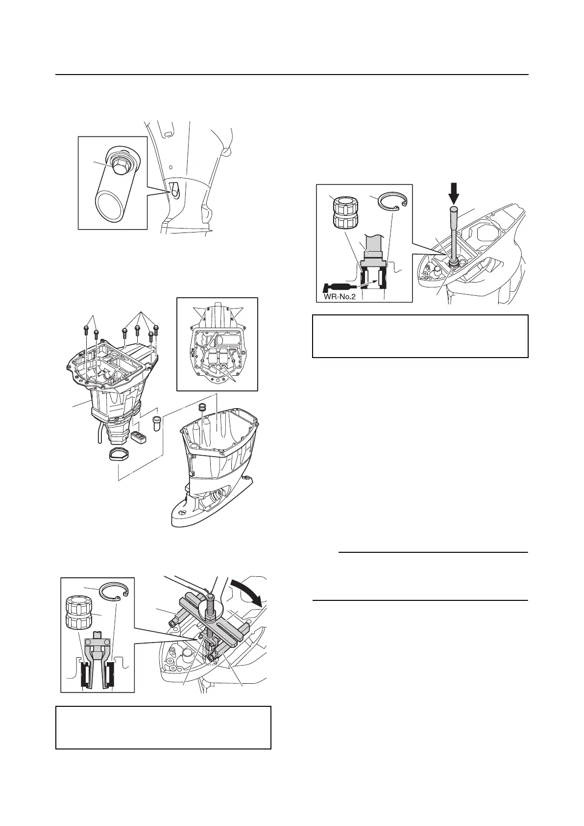
3. Remove the circlip “1”, and then remove
the bushing “2”.
Checking the drive shaft bushing
1. Check the bushing. Replace if cracked or
worn.
Assembling the upper case
1. Install the bushing “1”, and then install
the circlip “2”.
2. Install the dowels “1”.
3. Install the baffle plate “2”, and then
tighten the baffle plate screws “3” to the
specified torque.
4. Install the rubber seal “4” to the joint hole
“a” in the upper case.
5. Install a new rubber seal “5”, the rubber
seal “6”, and the damper “7”, and then
install the oil pan assembly “8”.
TIP:
Make sure to fit the tip of the cooling water
pipe “9” into the joint hole “a” in the upper
case.
6. Install the oil pan bolts “10” and “11”, and
then tighten them to the specified
torques.
Bearing puller assembly “3”: 90890-06535
Stopper guide stand “4”: 90890-06538
Stopper guide plate “5”: 90890-06501
1
1
1
2
2
2
3
1
2
3
4
4
5
Needle bearing attachment “3”:
90890-06653
Driver rod L3 “4”: 90890-06652
1
2
3
4
1
3

 Loading...