6-28
Throttle body and throttle link adjustment
0
1
2
3
4
5
6
7
8
9
10
A
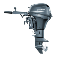
4. Loosen the TPS screws “1” and adjust
the position of the TPS “2” to get the
specified output voltage.
TIP:
• To increase the output voltage, turn the
TPS “2” in direction “a”.
• To decrease the output voltage, turn the
TPS “2” in direction “b”.
5. Tighten the TPS screws.
6. Operate the throttle valves several times
and check that the TPS output voltage is
within specification.
7. Tighten the synchronizing screw “1”
slowly until the TPS output voltage
begins to change.
8. Tighten the throttle stop screw “2” slowly
until the TPS output voltage is within
specification.
9. Start the engine and warm it up.
TIP:
Warm up the engine so that the engine tem-
perature displayed on the YDIS screen is
51 °C (123.8 °F) or more.
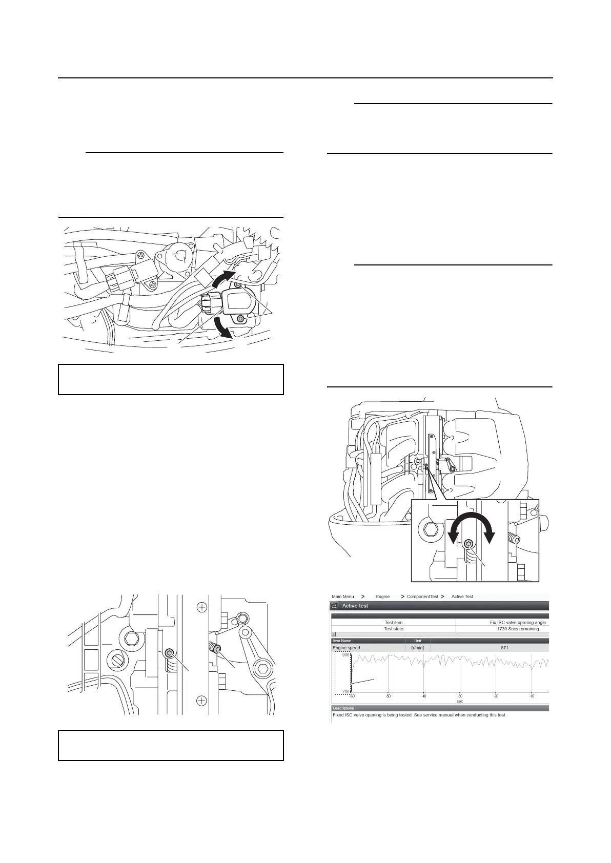
10. Perform the “Active test” using the YDIS
to fix the ISC valve.
11. Adjust the throttle stop screw “1” so that
the engine speed is 850 r/min.
TIP:
• To increase the engine speed, turn the
throttle stop screw “1” in direction “a”.
• To decrease the engine speed, turn the
throttle stop screw “1” in direction “b”.
• Set the Y axis “2” minimum range to 700
and the maximum range to 900 on the
graph to make the adjustment process eas-
ier.
12. Stop the engine.
13. Loosen the TPS screws “1” and adjust
the position of the TPS “2” to get the
specified output voltage.
TPS output voltage:
0.66 V
TPS output voltage:
0.70 ± 0.02 V
1
b
a
2
1
2
1
b
a
2

 Loading...