53
Replacing Parts
Replacing the Head Up Sensor
8/27/08 Thermal Transfer G-Series
TM
Service Manual 980618-001 A
Replacing the Head Up Sensor
You must remove the bottom case before performing this procedure.
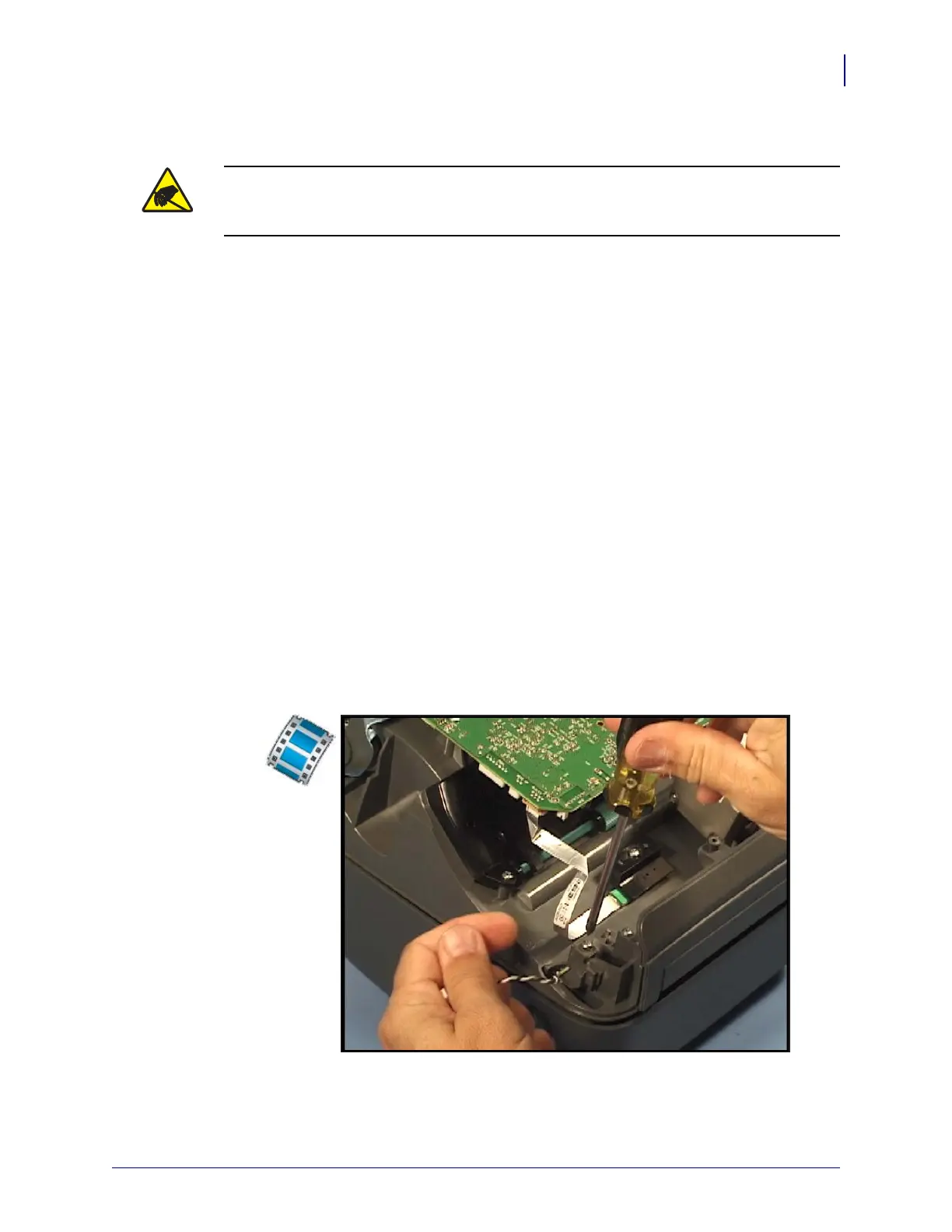
Removal
From beneath, the head up sensor is located on the left side of the printer towards the front of
the media compartment.
1. Carefully pull the sensor’s connector off of the Main Logic circuit board.
2. Use a #1 Phillips screwdriver to loosen the screw holding the head up sensor and bracket
to the inner mechanism.
3. Carefully lift the sensor and its wire bundle away from the printer.
Installation
1. Align the sensor into place with the guide facing forward.
2. Lower the sensor and its bracket into place.
3. Place the screw back into place and use a #1 Phillips screwdriver to tighten it.
4. Plug the wire bundle into its connector on the Main Logic circuit board.
Replace the bottom case. Reload media. Plug in power, turn on the printer and print a status
report to ensure proper function.
Caution • Prepare your work area by protecting against static discharge. Your work area
must be static-safe and include a properly grounded conductive cushioned mat to hold the
printer and a conductive wrist strap for yourself.
 Loading...