57
Replacing Parts
Replacing the Lower Moveable Gap/Blackline Sensor
8/27/08 Thermal Transfer G-Series
TM
Service Manual 980618-001 A
Replacing the Lower Moveable Gap/Blackline Sensor
The factory-installed optional moveable black line sensor allows the printer to use media with
off-center blackline(s), marks or notches (holes).
You must remove the bottom case, Main Logic circuit board and motor before performing this
procedure.
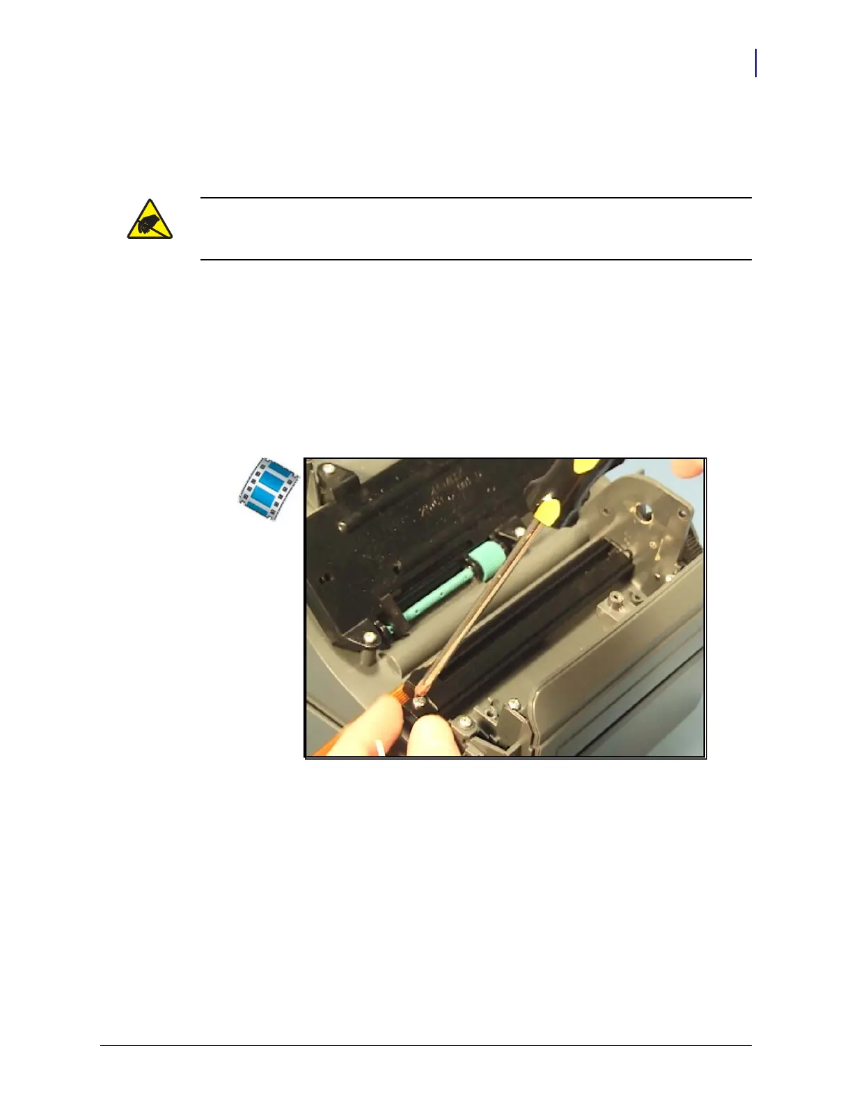
Removal
1. From beneath, use #1 Phillips screwdriver to loosen the screw holding the sensor’s bracket
track to the inner, bottom frame.
2. Carefully lift the sensor and bracket track away from and out of the side wall of the
printer’s chassis.
Installation
1. Place the sensor in the middle of the sensor’s slide which is track molded into the printer’s
chassis.
2. Align the bracket track so that its two slide tracks align up with the two metal springs on
the back of the sensor. Slide the bracket track’s capture and alignment pin s into the
printer’s chassis wall. Align the screw mounting hole on the opposite end of the bracket
track to chassis’s bracket mounting post and snap it to the chassis.
3. Replace the screw that held the bracket track with a #1 Phillips screwdriver. Make sure the
sensor and cable slide in its track.
Replace the motor, Main Logic circuit board and bottom case. Reload media. Plug in power,
turn on the printer and print a status report to ensure proper function.
Caution • Prepare your work area by protecting against static discharge. Your work area
must be static-safe and include a properly grounded conductive cushioned mat to hold the
printer and a conductive wrist strap for yourself.
 Loading...