63
Replacing Parts
Replacing the Cutter (Option)
8/27/08 Thermal Transfer G-Series
TM
Service Manual 980618-001 A
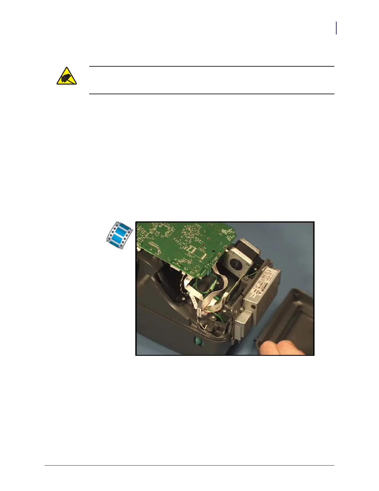
Replacing the Cutter (Option)
You must remove the bottom case before performing this procedure.
Removal of the bezel
The cutter is located on the front of the printer below the media exit.
1. With the printer upside down, carefully pull the cutter’s connector off of the Main Logic
circuit board.
2. Disconnect the cutter’s ground wire from the ‘Y’ connector joining the cutter and motor
ground wires to connect to the Main Logic circuit board.
3. Use a #1 Phillips screwdriver to loosen and remove the screws on the left and right sides
behind the cutter mount. Lift the cutter away from the printer.
Installation of the mechanism
1. Replace the cutter’s circuit board.
2. From behind the cutter, lower the circuit board onto the mechanism.
3. Replace the screws and use a #1 Phillips screwdriver to tighten them.
4. Plug the mechanism’s wire bundle into its connector on the cutter circuit board.
5. Check routing of the wires and make sure they are clear of the cutter cover.
Caution • Prepare your work area by protecting against static discharge. Your work area
must be static-safe and include a properly grounded conductive cushioned mat to hold the
printer and a conductive wrist strap for yourself.
 Loading...