that is not connected to a symbol may be done in any line width in the range 1 - 5. But
it needs to be simple connection points to be drawn.
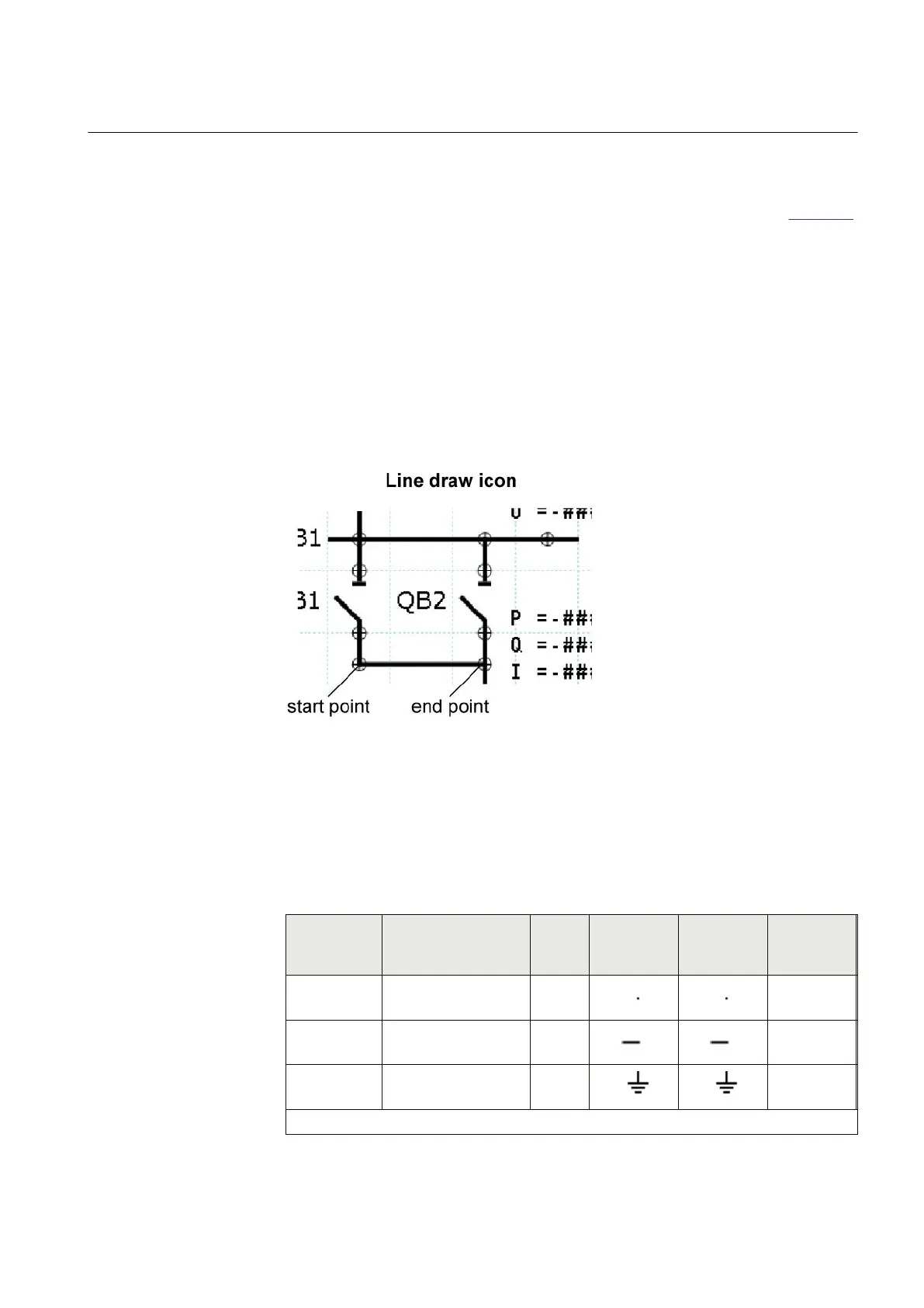
For the procedure to draw lines when the apparatus symbols are placed, see Figure 56.
1. Place the apparatus or transformer symbols by drag and drop in a raster box.
2. Place the connections symbols by drag and drop in a raster box.
3. Click the Link icon to enable direct line drawing.
4. Center the mouse pointer on the center of a connection point; visible in two circles
at the endpoints of a line, to draw a line.
5. Click to start and move the mouse pointer to the destination connection point.
Center once again the mouse pointer and click to drop the line.
6. Draw all line elements that are necessary.
7. Click Select in the menu bar to finish the line drawing.
IEC05000598 V2 EN
Figure 56: GDE: Drawing a line
6.2.2 Supported single-line diagram symbols
Table 6: Supported symbols
Category
IEC Symbol Name Symbol
Type
IEC Symbol
Definitions
ANSI Y32.2/
IEEE 315
Symbol
Definitions
Function Block
Type
Connections Junction 1
Connections Busbar junction 2
Connections Earth 10
Table continues on next page
1MRK 511 284-UEN A Section 6
Local HMI engineering
650 series 77
Engineering manual
 Loading...

