This document adds the following points to the still valid existing documentation:
● Unavoidable device deviations, e.g. due to technical limitations.
● Expansion of documentation as a result of normative requirements.
● Additional contents not described in the existing documentation.
Further information on replacement device DC501-CS31-AD can be found in the operating and
assembly instructions of device DC501-CS31-AD: 3ADR020087M0401. Please note that for
device DC501-CS31 no separate operating and assembly instructions are available.
Please also observe the system data as well as the information on CS31 bus
Ä
Chapter 1.3
“System data and CS31 bus system data” on page 4.
1.5.6.2 Device configuration
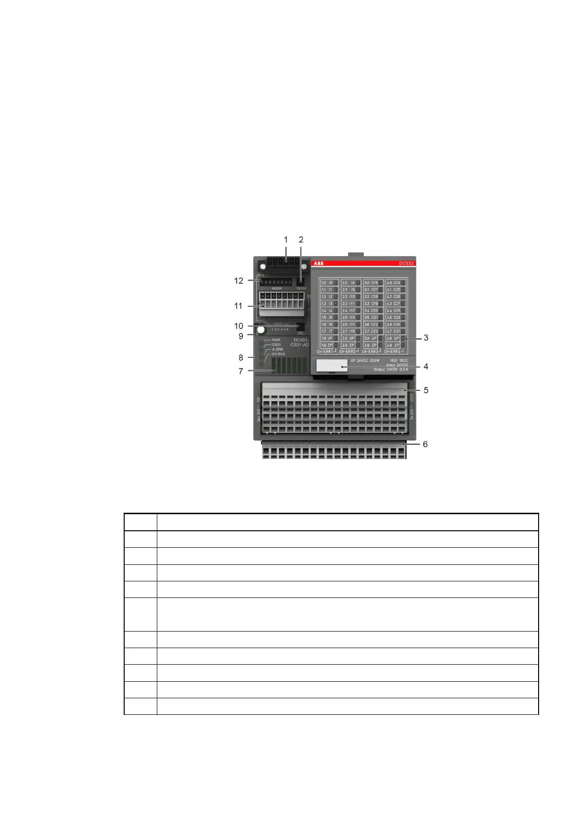
Fig. 85: Front view: DC501-CS31-AD
Table 80: Device configuration:
No. Description
1 Connection for CS31 bus (X1)
2 Bus termination (CS31 bus)
3 Status LEDs for DC532
4 TA525: Label
5 Terminals signal level (X4)
16 digital inputs, 8 digital outputs, 8 DC voltage supply (incl. DC532)
6 Terminals signal level (plug-in power bus)
7 Ventilation
8 4 Status LEDs
9 Hole for screw mounting (screw diameter 4 mm, extension torque 1.2 Nm)
10 Function selector switch for I/O expansion
Replacement devices: I/O modules > Replacement unit DC501-CS31-AD
2018/09/243ADR010122, 8, en_US138
 Loading...