In contrast to the existing device, the following measuring ranges are not avail-
able in the replacement device:
±
500 mV,
±
50 mV. Temperature measurement
with thermocouples is also not possible.
The replacement device does not perform a self-calibration.
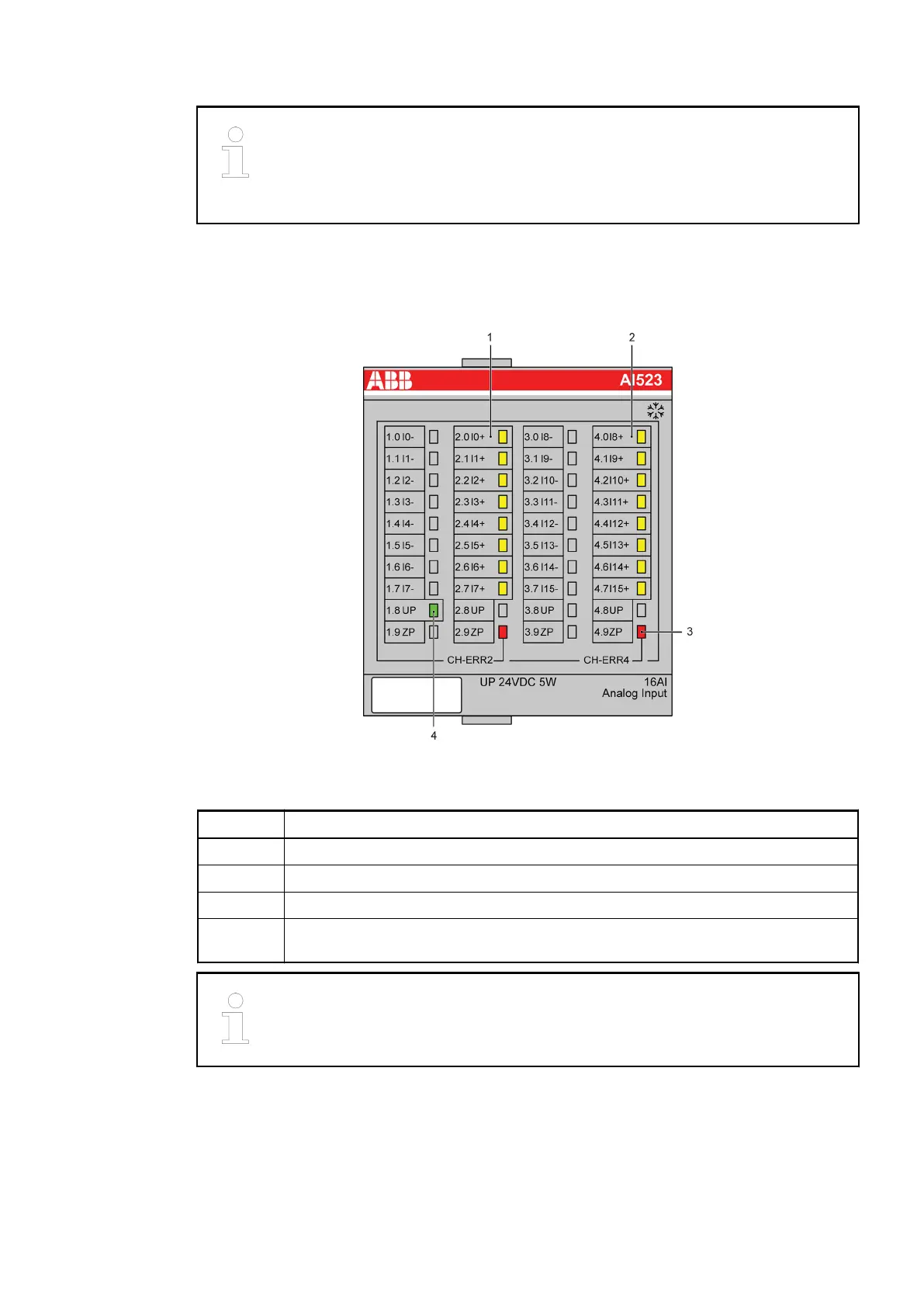
1.5.3.2.1 LED display
The LED display on the replacement device is changed:
Fig. 57: Front view: 07AI91-AD
No. Display of module
1 8 yellow LEDs to indicate the signal status of the analog inputs (X2 and X3)
2 8 yellow LEDs to indicate the signal status of the analog inputs (X5 and X6)
3 2 red LEDs to indicate errors (of AI523 module)
4 1 green LED to indicated the status of the supply voltage of the AI523 module (is
supplied via X4)
The replacement device does not provide a test button to measure functionality.
Replacement devices: I/O modules > Replacement device 07AI91-AD
2018/09/243ADR010122, 8, en_US90
 Loading...