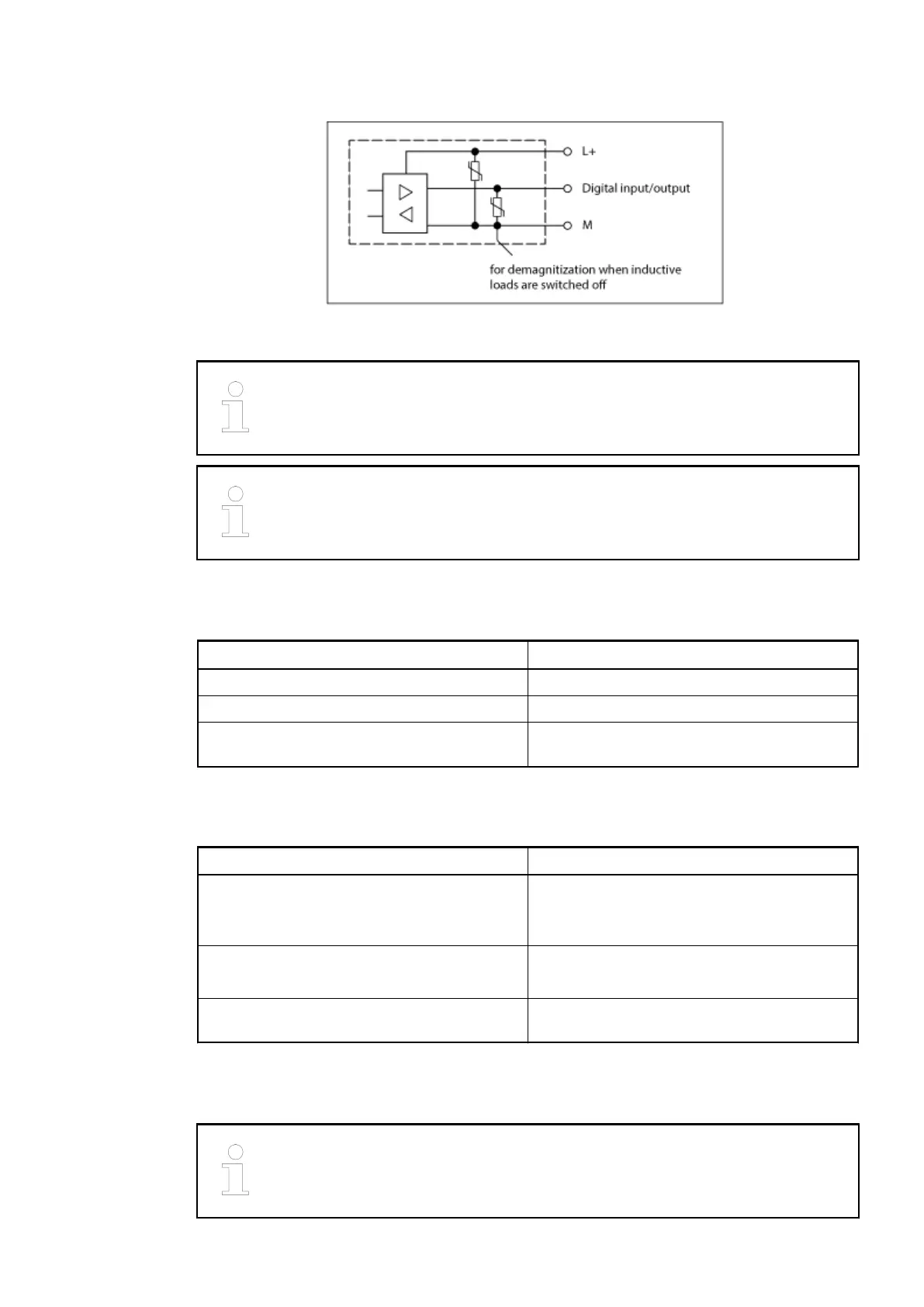
Fig. 44: Protective circuits inputs/outputs
Due to the changed protective circuit on the inputs and outputs, the restrictions
concerning the input signal voltage described in the existing documentation no
longer apply.
When the channels of connector X6 are to be used as inputs, the respective
outputs (high-end switches) must be switched off.
1.5.1.8.5 Connection to the CS31 bus
Data Value
Connections X1/B2, X1/B1
CS31 bus type 04 (digital input/output)
Termination resistor Not available (must be provided externally if
needed)
1.5.1.8.6 Mechanical data
Data Value
Width x height x depth Replacement device: 120 x 140 x approx. 80
mm
Existing device: 120 x 140 x 85 mm
Weight Replacement device: 351 g (incl. terminals)
Existing device: 450 g
Dimensions for mounting See operating and assembly instructions of
the replacement device (3ADR020083M0401)
1.5.1.8.7 Assembly / Disassembly
The dimensions for the assembly holes are the same for the replacement
device and the existing device.
Replacement devices: I/O modules > Replacement device 07DC91-AD
2018/09/24 3ADR010122, 8, en_US 71
 Loading...