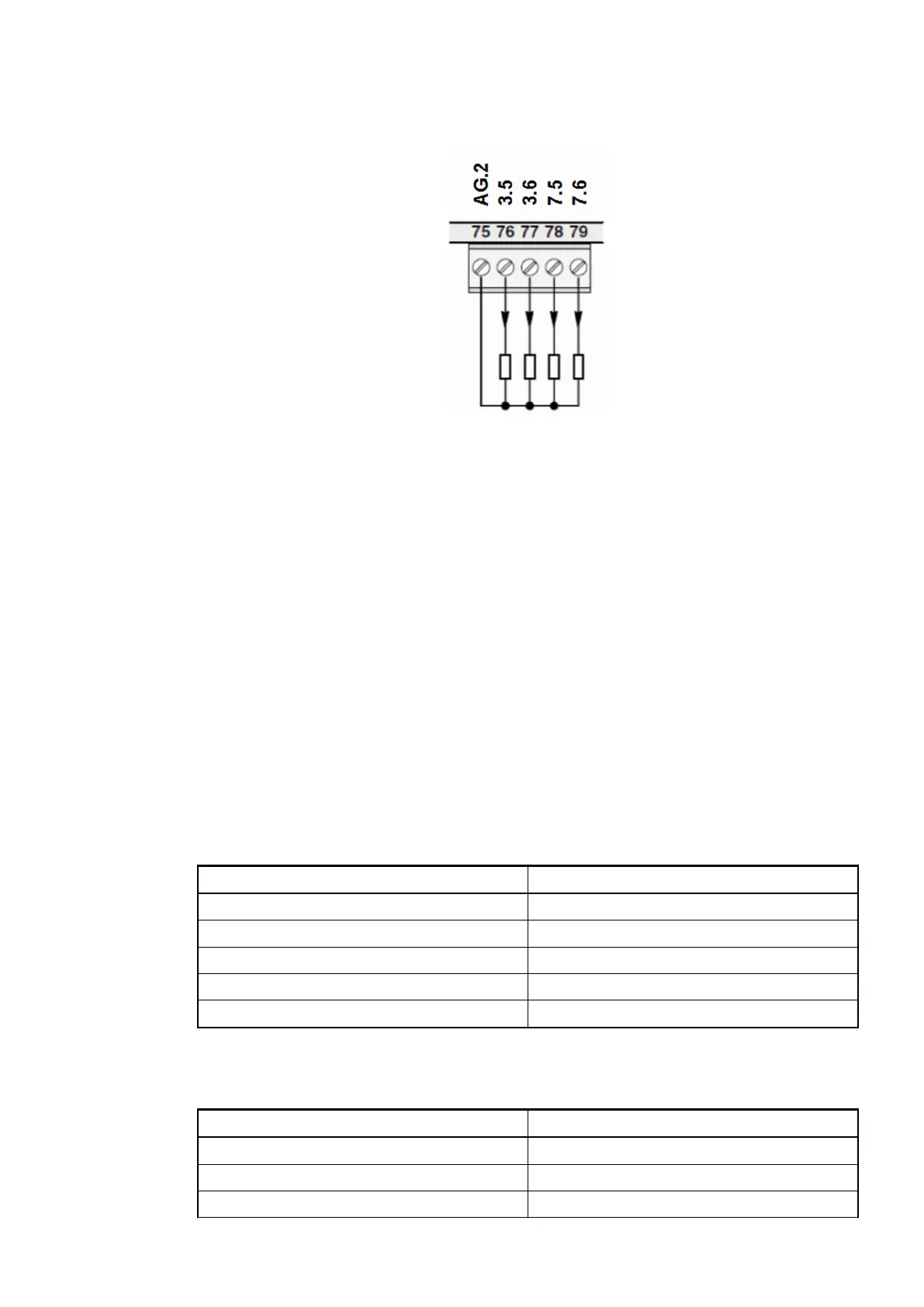
No change to the wiring is necessary. The sensor is connected the same way as with the
existing device 07KT98. Output load capability of voltage output: max. ±10 mA.
Fig. 34: Connection of output loads (voltage and current) to analog outputs
Battery and battery replacement
The AC31 adapters use another battery (lithium battery TA521).
For further information, please refer to the AC500 documentation.
Serial interface COM1
The serial interface COM1 is no longer available.
Programming can be performed via the serial interface COM2.
The serial interface DIAG is used for diagnosis and configuration. The DIAG interface is not
electrically isolated and thus only intended for connection with the Automation Builder.
In the CPU or Automation Builder, the DIAG interface is accessed via the FBP interface. Conse-
quently, the information of the DIAG interface appears on the CPU display under the FBP inter-
face.
Connector / Pin Assignment / Signal
DIAG / 1 Not connected
DIAG / 2 TX
DIAG / 3 M
DIAG / 4 RX
DIAG / 5 FE
Serial interface COM2
Connector / Pin Assignment / Signal
COM2 / 1 FE
COM2 / 2 TX
COM2 / 3 RX
Output areas
±10 V / 0 ... 20
mA / 4 ... 20 mA
Serial interface
DIAG
Replacement devices: CPU > Replacement device 07KT9x-AD
2018/09/243ADR010122, 8, en_US42
 Loading...