Connector / Terminal Pin Assignment / Signal
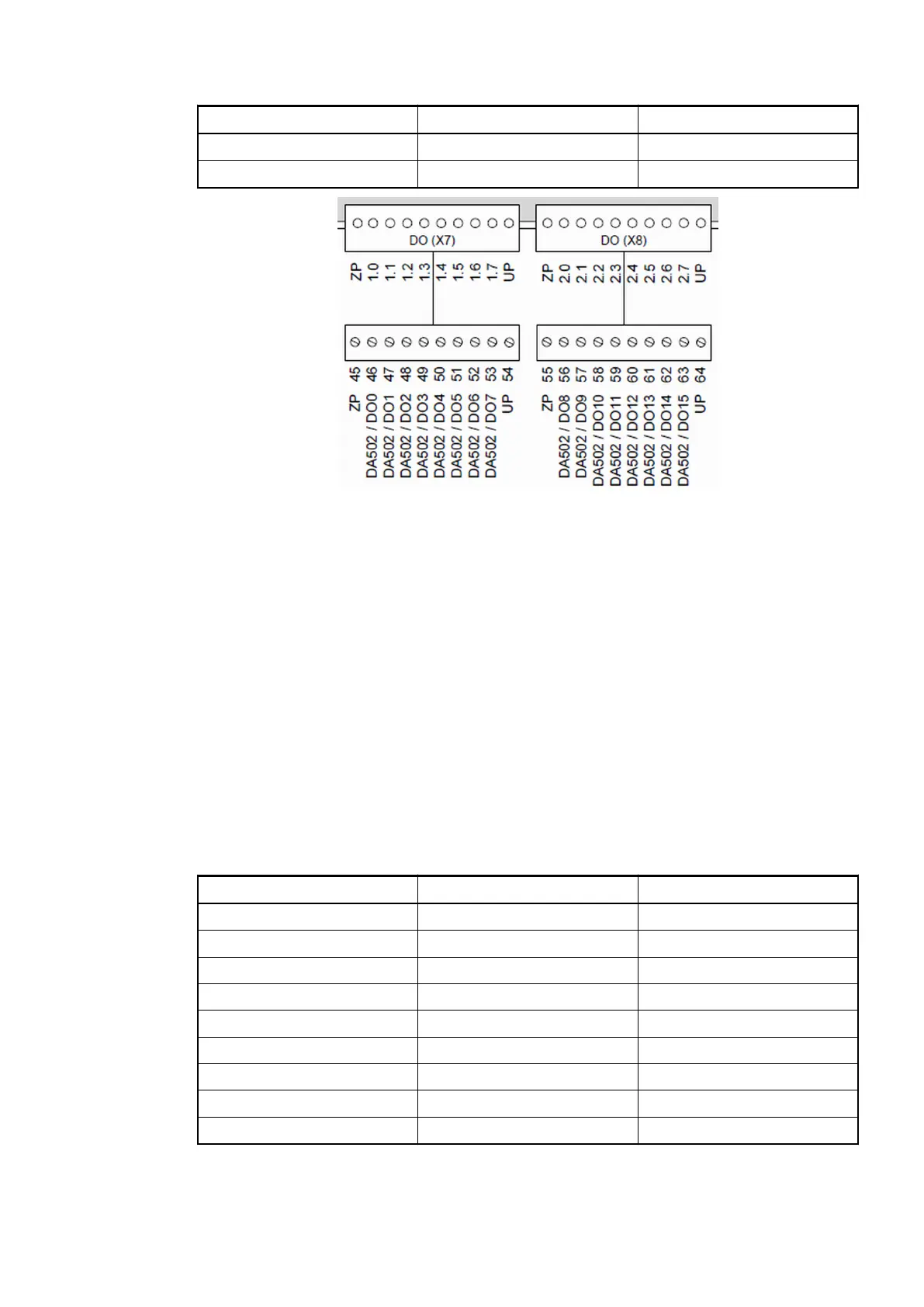
X8 / 2.7 63 DA502 / DO15
X8 / UP 64 UP
Fig. 23: Arrangement of digital outputs
Characteristics of the digital outputs
● The digital output states are always indicated by the LEDs DO0-DO15 on DA501 module.
● All 16 outputs have the same potential ZP as all other inputs/outputs. The electrical isolation
included in the existing devices is no longer available.
● Diagnosis: Stored errors are indicated via an LED and can be accessed by the CPU (see
AC500 documentation).
Circuit arrangement of digital outputs
● Fig. 22
●
Ä
Further information on page 32
Connection of the digital inputs/outputs
Table 18: Connector (X1)
Connector / Terminal Pin Assignment / Signal
X1 / ZP 1 ZP
X1 / 4.0 2 DA502 / DC16
X1 / 4.1 3 DA502 / DC17
X1 / 4.2 4 DA502 / DC18
X1 / 4.3 5 DA502 / DC19
X1 / 4.4 6 DA502 / DC20
X1 / 4.5 7 DA502 / DC21
X1 / 4.6 8 DA502 / DC22
X1 / 4.7 9 DA502 / DC23
Replacement devices: CPU > Replacement device 07KT9x-AD
2018/09/243ADR010122, 8, en_US30