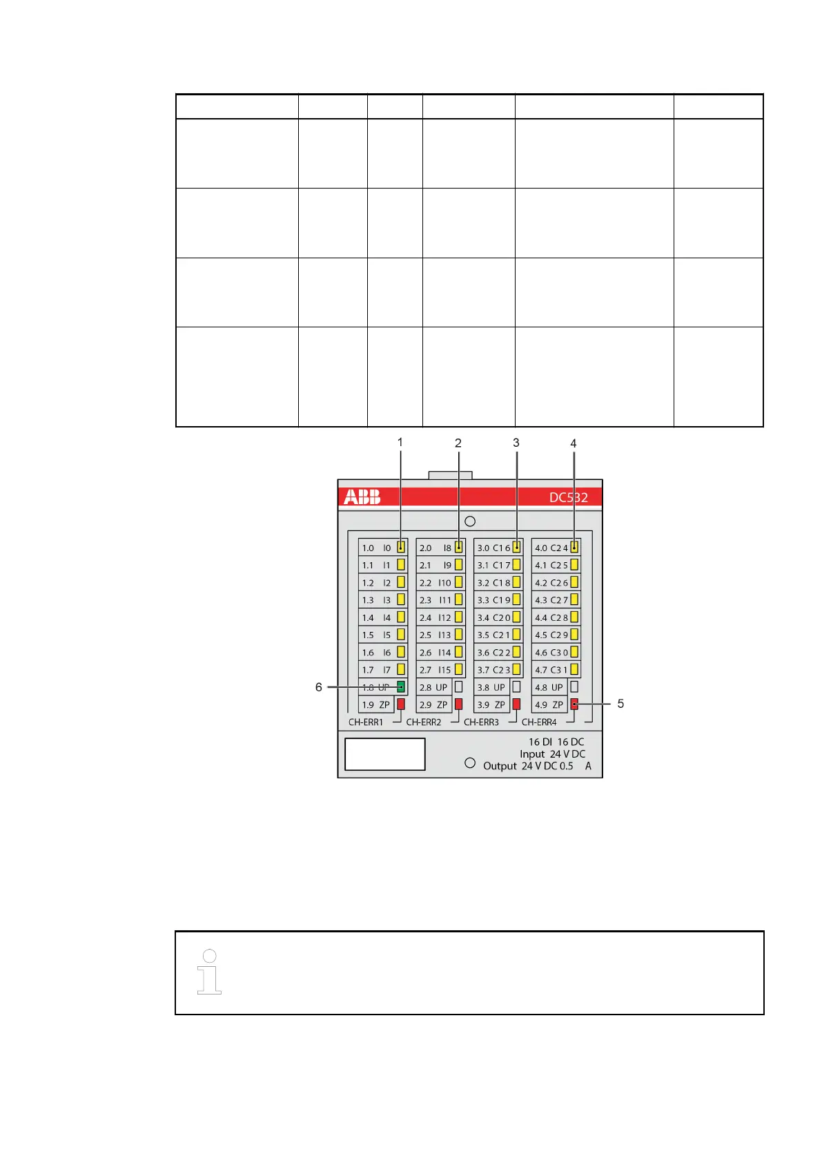
LED Status Color LED off LED on LED flashes
C24…C31 (see
No. 4 in the fol-
lowing figure)
Digital
inputs or
digital
outputs
Yellow Input or
output is not
activated
Input/output is activated
(input voltage is indi-
cated even if supply is
switched off)
-
Indication supply
voltage (see No. 6
in the following
figure)
Process
voltage
Green Process
voltage not
available
Process voltage OK -
Error indications
left (see No. 5 in
the following
figure)
Error
indication
Red No error Internal error
Error indications
right (see No. 5 in
the following
figure)
Error
indication
Red No error Internal error Overload or
short circuit
on a channel
of the corre-
sponding
group
Fig. 97: Front view: DC532
1.5.6.2.6 Technical data
This section expands the details provided in the chapter
Ä
Chapter 1.3 “System data and CS31
bus system data” on page 4 and contains information on electromagnetic compatibility. The con-
formity is described in the declaration of conformity, which is available on the ABB website.
To ensure proper function of the replacement device DC501-CS31-AD, both
supply voltages Vs+ and V+ must be applied.
Replacement devices: I/O modules > Replacement unit DC501-CS31-AD
2018/09/243ADR010122, 8, en_US152
 Loading...