1.5.2.8.3 Technical details of the I/O channels as digital outputs
Data Value
Connections X2 / 1.0 to 1.7
X3 / 2.0 to 2.7
X5 / 3.0 to 3.7
X6 / 4.0 to 4.7
Type of digital outputs High-side switch
Reference potentials for the outputs M (07DC92: ZP0, ZP1, ZP2 and ZP3)
Supply voltage for the outputs L+ (07DC92: UP0, UP1, UP2 and UP3)
Electrical isolation No (07DC92: Group against group, all groups
in relation to the rest of the device
Output current (maximum value) X2 + X3 = 4 A, X5 + X6 = 4 A (07DC92: 4 A
per group)
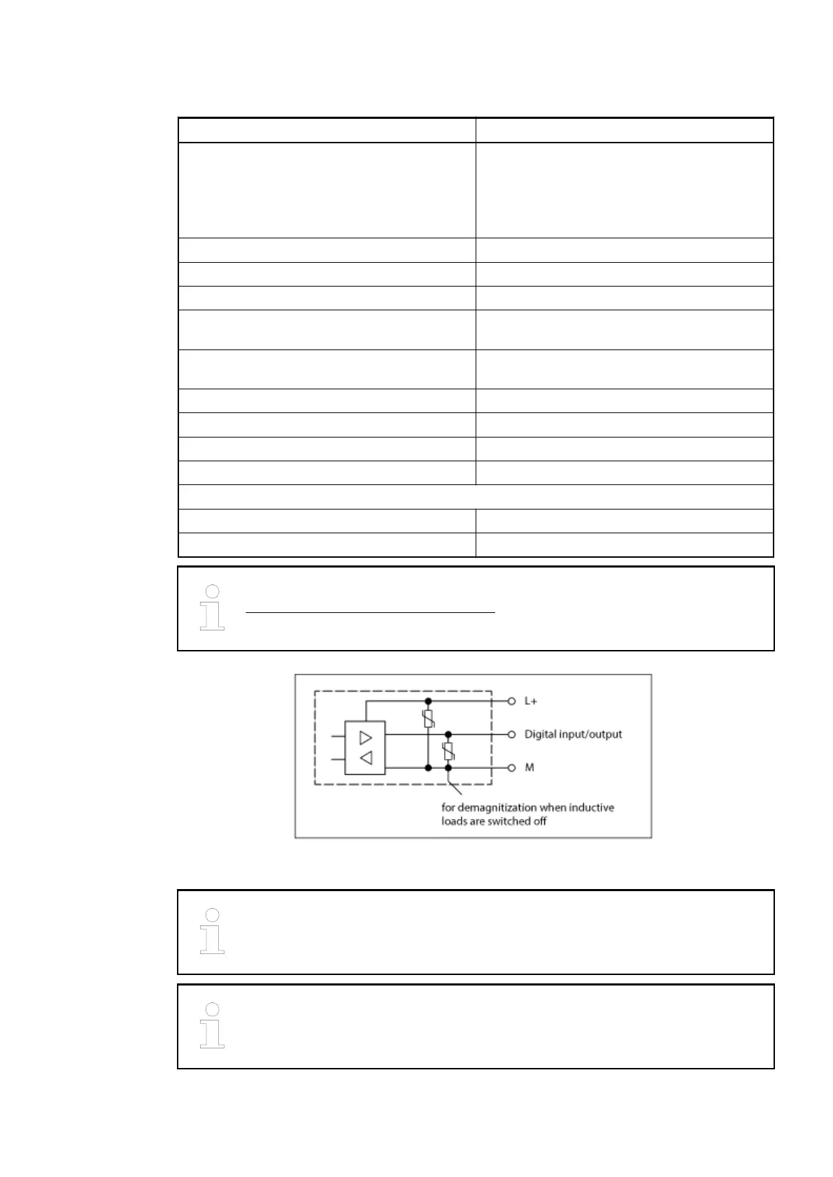
Demagnetization with inductive load Internally with a varistor (with other circuitry)
Switching frequency with ohmic load On request
Output voltage at signal 1 X4 / L+ (typ. 24 V) -0.8 V
Output delay: 0 -> 1 or 1 -> 0 On request
Maximum cable length:
-> Shielded 1000 m
-> Unshielded 600 m
For further information, please refer to the existing documentation
System description Advant Controller 31.
Fig. 54: Protective circuits inputs/outputs
Due to the changed protective circuit on the inputs and outputs, the restrictions
concerning the input signal voltage described in the existing documentation no
longer apply.
If the channels are to be used as inputs, the respective outputs (high-side
switches) must be switched off.
Replacement devices: I/O modules > Replacement device 07DC92-AD
2018/09/243ADR010122, 8, en_US86
 Loading...