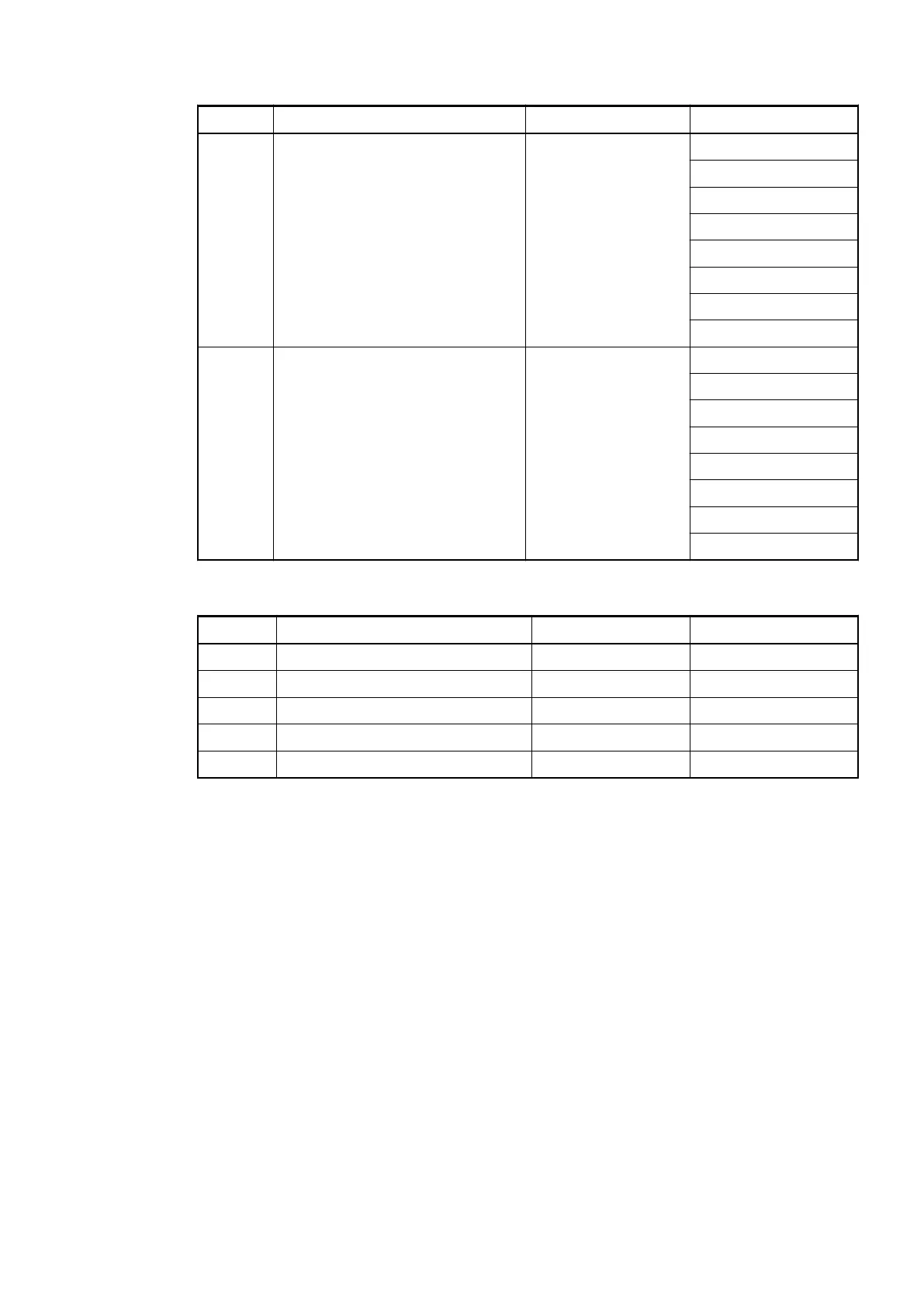
Byte Type Bit Connector / Terminal
3 8 bit output (receive) 0 ... 7 X5 / 3.0
X5 / 3.1
X5 / 3.2
X5 / 3.3
X5 / 3.4
X5 / 3.5
X5 / 3.6
X5 / 3.7
4 8 bit output (receive) 0 ... 7 X6 / 4.0
X6 / 4.1
X6 / 4.2
X6 / 4.3
X6 / 4.4
X6 / 4.5
X6 / 4.6
X6 / 4.7
Table 33: CS31 bus (24 inputs / 16 outputs)
Byte Type Bit Connector / Terminal
1 8 bit input (send) 0 ... 7 X2 / 1.0 ... 1.7
2 8 bit input (send) 0 ... 7 X3 / 2.0 ... 2.7
3 8 bit output (receive) 0 ... 7 X5 / 3.0 ... 3.7
4 8 bit input (send) 0 ... 7 X6 / 4.0 ... 4.7
5 8 bit output (receive) 0 ... 7 X6 / 4.0 ... 4.7
1.5.1.5 I/O configuration
The existing device had a DIP switch on the upper printed circuit board. Since the replacement
device is not equipped with an upper printed circuit board, the DIP switch is arranged on the
lower printed circuit board instead.
Replacement devices: I/O modules > Replacement device 07DC91-AD
2018/09/243ADR010122, 8, en_US64