1.5.3.2 Device configuration
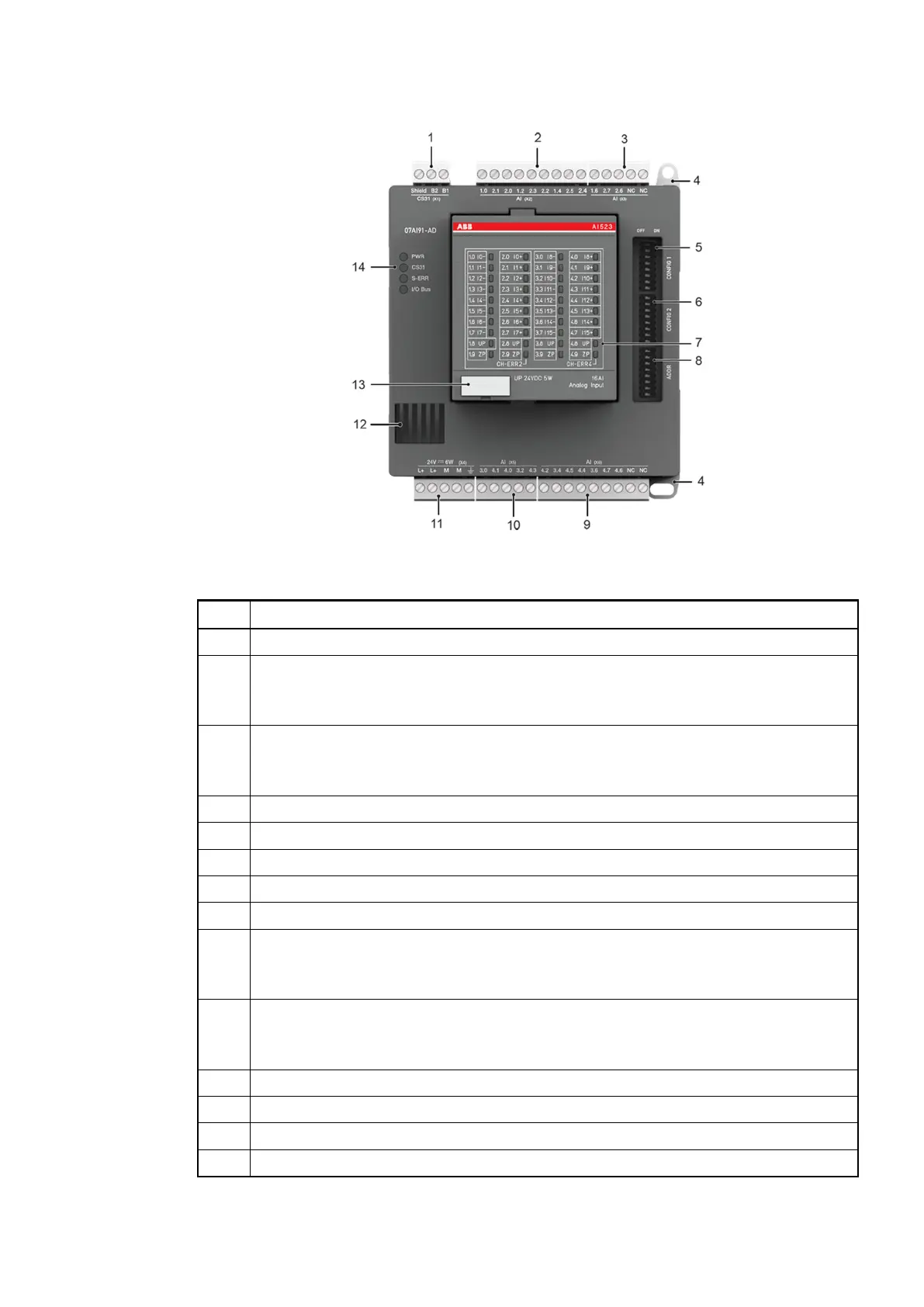
Fig. 56: Front view: 07AI91-AD
No. Description
1 Connection for CS31 bus (X1)
2 Analog inputs (X2)
2.5 AI (± 10 V differential, ± 5 V differential, temperature measurement PT100 /
PT1000, 4…20 mA and 0…20 mA with external resistor)
3 Analog inputs (X3)
1.5 AI (± 10 V differential, ± 5 V differential, temperature measurement PT100 /
PT1000, 4…20 mA and 0…20 mA with external resistor)
4 Hole for screw mounting (screw diameter 4 mm, extension torque 1.2 Nm)
5 DIP switch for CONFIG1
6 DIP switch for CONFIG2
7 Status LEDs for AI523
8 DIP switch for ADDR
9 Analog inputs (X6)
2.5 AI (± 10 V differential, ± 5 V differential, temperature measurement PT100 /
PT1000, 4…20 mA and 0…20 mA with external resistor)
10 Analog inputs (X5)
1.5 AI (± 10 V differential, ± 5 V differential, temperature measurement PT100 /
PT1000, 4…20 mA and 0…20 mA with external resistor)
11 Supply 24 V DC (incl. AI523)
12 Ventilation
13 TA525: Label
14 4 Status LEDs of complete device
Replacement devices: I/O modules > Replacement device 07AI91-AD
2018/09/24 3ADR010122, 8, en_US 89
 Loading...