Program features 153
Load analyzer
The load analyzer can be used for analyzing the customer’s process and sizing the
drive and the motor.
Peak value logger
The user can select a signal (group 01 OPERATING DATA) to be monitored by the
peak value logger (PVL). The signal is sampled at 2 ms intervals when the drive is
running. The logger records the peak (maximum) value of the signal along with the
time the peak occurred, as well as output current, DC voltage and output frequency at
the time of the peak.
Amplitude loggers
The drive has two amplitude loggers.
For amplitude logger 2 (AL2), the user can select a signal (group 01 OPERATING
DATA) to be sampled at 200 ms intervals when the drive is running, and specify a
value that corresponds to 100%. The collected samples are sorted into 10 read-only
parameters according to their amplitude. Each parameter represents an amplitude
range 10 percentage points wide, and displays the percentage of the collected
samples that fall within that range.
Amplitude logger 1 (AL1) is fixed to monitor output current, and it cannot be reset.
With amplitude logger 1, 100% corresponds to the nominal output current of the drive
(I
2N
).
The peak value logger and amplitude logger 2 can be reset by a user-defined
method. They are also reset if either of the signals or the peak value filter time is
changed.
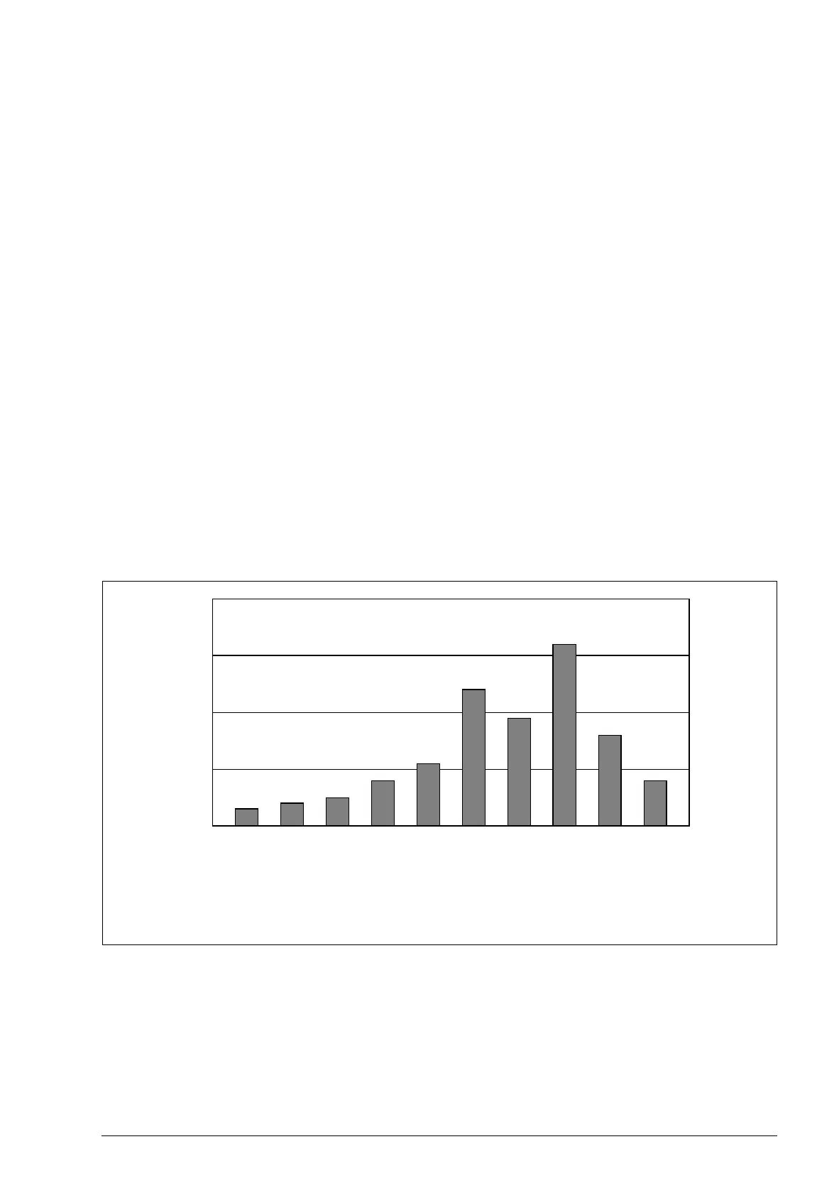
Percentage of samples
0…10%
10…20%
20…30%
30…40%
40…50%
50…60%
60…70%
70…80%
80…90%
>90%
Amplitude ranges (parameters 6414…6423)