Application macros 105
3-wire macro
This macro is used when the drive is controlled using momentary push-buttons. It
provides three constant speeds. To enable the macro, set the value of parameter
9902 APPLIC MACRO to 2 (3-WIRE).
For the parameter default values, see section Default values with different macros on
page 165. If you use other than the default connections presented below, see section
I/O terminals on page 49.
Note: When the stop input (DI2) is deactivated (no input), the control panel start and
stop buttons are disabled.
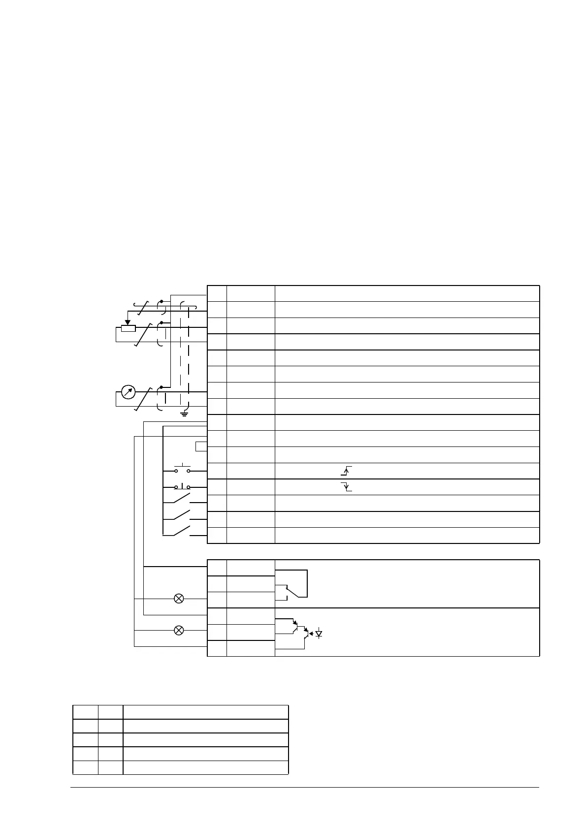
Default I/O connections
X1A
1 SCR Signal cable shield (screen)
2AI1 Output frequency reference: 0…10 V
3 GND Analog input circuit common
4 +10V Reference voltage: +10 V DC, max. 10 mA
5 AI2 Not in use by default. 0…10 V
6 GND Analog input circuit common
7AO Output frequency value: 0…20 mA
8 GND Analog output circuit common
9 +24V Auxiliary voltage output: +24 V DC, max. 200 mA
10 GND Auxiliary voltage output common
11 DCOM Digital input common
12 DI1 Start (pulse )
13 DI2 Stop (pulse )
14 DI3 Forward (0) / Reverse (1)
15 DI4 Constant speed selection
1)
16 DI5 Constant speed selection
1)
X1B
17 ROCOM Relay output 1
No fault [Fault (-1)]
18 RONC
19 RONO
20 DOSRC Digital output, max. 100 mA
No fault [Fault (-1)]
21 DOOUT
22 DOGND
max. 500 ohm
1…10 kohm
2)
1)
See parameter group 12 CONSTANT
SPEEDS:
2)
360 degree grounding under a clamp.
Tightening torque: 0.4 N·m (3.5 lbf·in).
DI3 DI4 Operation (parameter)
0 0 Set speed through AI1
1 0 Speed 1 (1202
CONST SPEED 1)
0 1 Speed 2 (1203
CONST SPEED 2)
1 1 Speed 3 (1204
CONST SPEED 3)

 Loading...


