Control panels 77
How to select the monitored signals
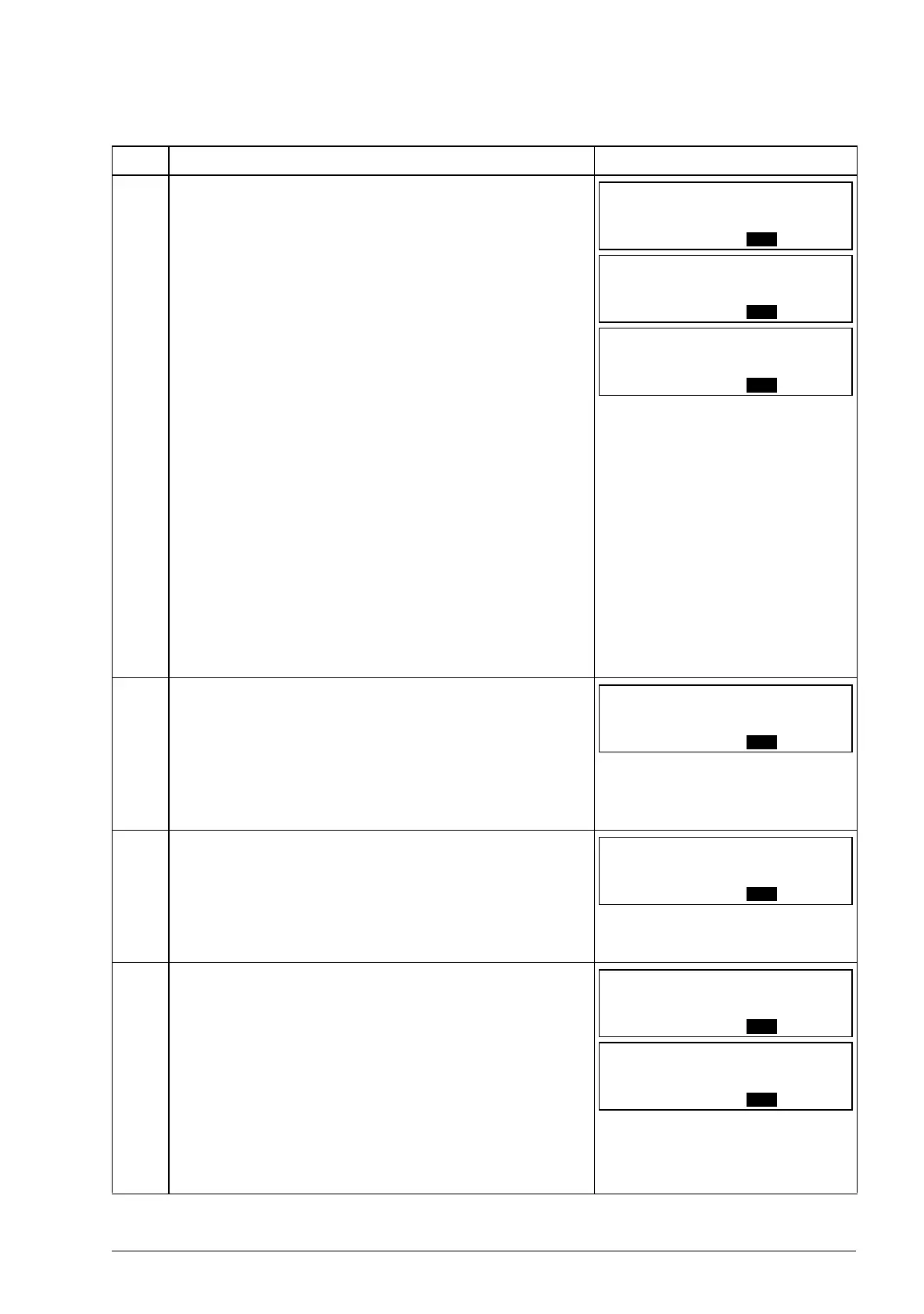
Step Action Display
1. You can select which signals are monitored in the
Output mode and how they are displayed with group
34 PANEL DISPLAY parameters. See page 76 for
detailed instructions on changing parameter values.
By default, the display shows three signals:
Signal 1: 0103 OUTPUT FREQ
Signal 2: 0104 CURRENT
Signal 3: 0105 TORQUE
To change the default signals, select up to three
signals from group 01 OPERATING DATA to be
shown.
Signal 1: Change the value of parameter 3401
SIGNAL1 PARAM to the index of the signal
parameter in group 01 OPERATING DATA
(= number of the parameter without the leading
zero), for example, 105 means parameter 0105
TORQUE. Value 100 means that no signal is
displayed.
Repeat for signals 2 (3408 SIGNAL2 PARAM) and 3
(3415 SIGNAL3 PARAM). For example, if 3401 = 0
and 3415 = 0, browsing is disabled and only the
signal specified by 3408 appears in the display. If all
three parameters are set to 0, ie no signals are
selected for monitoring, the panel displays text “n.A”.
2. Specify the decimal point location, or use the decimal
point location and unit of the source signal (setting 9
[DIRECT]). Bar graphs are not available for basic
control panel. For details, see parameter 3404.
Signal 1: parameter 3404 OUTPUT1 DSP FORM
Signal 2: parameter 3411 OUTPUT2 DSP FORM
Signal 3: parameter 3418 OUTPUT3 DSP FORM.
3. Select the units to be displayed for the signals. This
has no effect if parameter 3404/3411/3418 is set to 9
(DIRECT). For details, see parameter 3405.
Signal 1: parameter 3405 OUTPUT1 UNIT
Signal 2: parameter 3412 OUTPUT2 UNIT
Signal 3: parameter 3419 OUTPUT3 UNIT.
4. Select the scalings for the signals by specifying the
minimum and maximum display values. This has no
effect if parameter 3404/3411/3418 is set to 9
(DIRECT). For details, see parameters 3406 and
3407.
Signal 1: parameters 3406 OUTPUT1 MIN and 3407
OUTPUT1 MAX
Signal 2: parameters 3413 OUTPUT2 MIN and 3414
OUTPUT2 MAX
Signal 3: parameters 3420 OUTPUT3 MIN and 3421
OUTPUT3 MAX.

 Loading...


