Advant Controller 450 Product Guide
Chapter 5 Mechanical Design
5-4 3BSE 015 953R201 Rev B
Advant Controller 450 with S100 I/O in RM500V2 Cabinets
• The delivery is assembled in up to six cabinets, for the controller subrack and the five
possible I/O subracks that can be connected to the same bus extension.
• With the cabinet housing the controller subrack to the left, the building direction is to
the right.
• Cabinet no 2, 4 and 6 contain no hinged frame.
• Modems are always placed in cabinet no 1 in a modem subrack. For maximum four
modems, mounting plates to the left of the controller subrack is used.
• All cabinets that share the same S100 I/O bus extension (max 12m) are connected to
the same power switch placed in the cabinet housing the controller subrack.
• Cabinet no. 1, 3 and 5 have their own power supplies (power switch in cabinet no 1).
• One set of power supplies for field equipment, if ordered, is placed in cabinet no 2.
• Connection units are placed only within the same single or double cabinet that houses
the corresponding I/O subrack or in the next cabinet to the right.
• The boards are placed in the I/O subracks in the order AI, AO, DO, DI starting in subrack
no 1.
NOTE
DI boards are the last group. Connection units for higher voltage than 24 V
occupies more space than the corresponding units for 24 V.
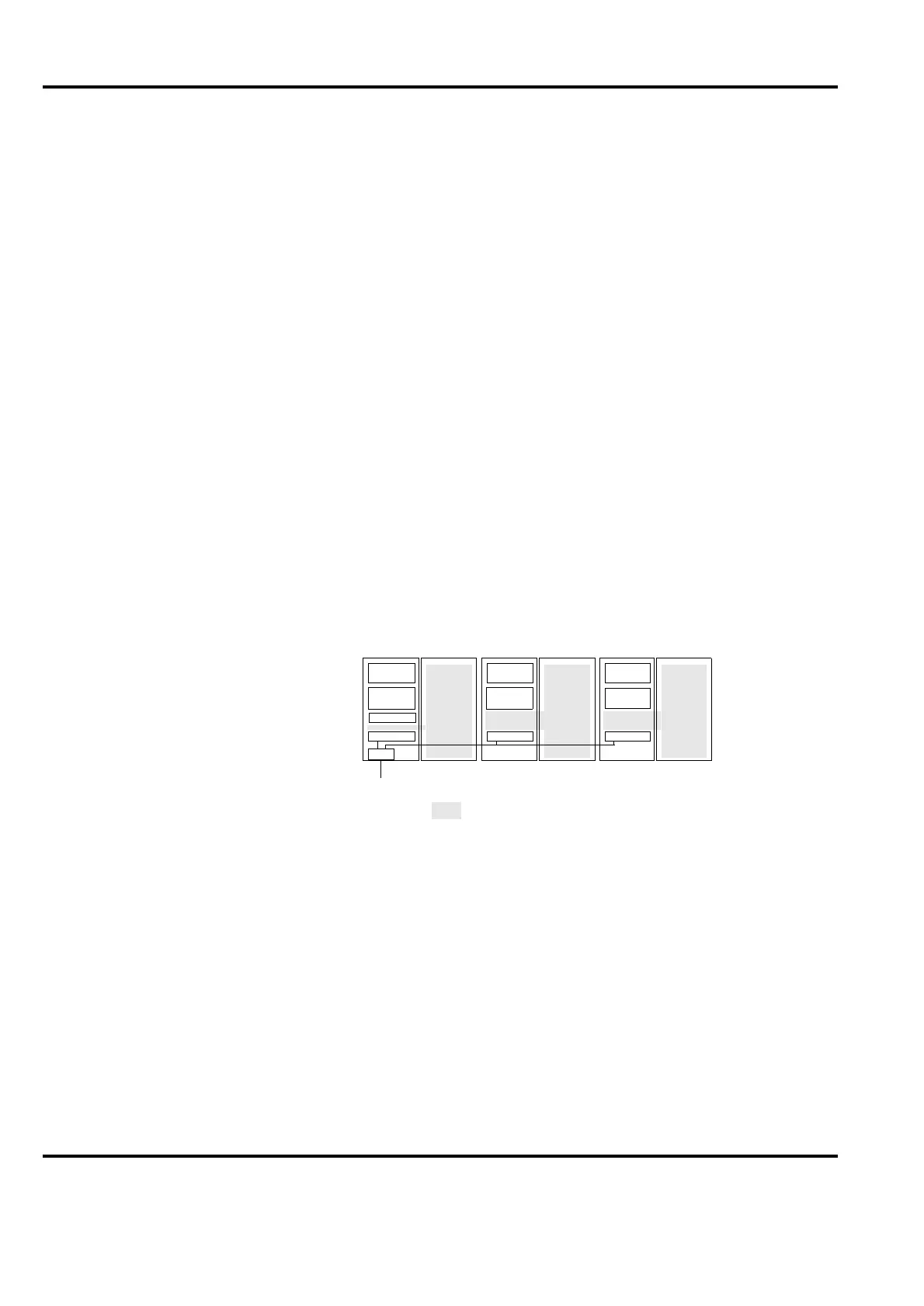
Figure 5-3. Maximum cabinet configuration for Advant Controller 450 with S100 I/O
assembled in RM500V2 cabinets
PS
SW
Mains
CTR
I/O 1
PS
I/O 2
I/O 3
Conn.
units
PS Power Supply
SW Power Switch
PS
I/O 4
12 3 4 5 6
I/O 5
 Loading...


