10 AWT420 | UNIVERSAL 4-WIRE, DUAL-INPUT TRANSMITTER | OI/AWT420-EN REV. B
…4 Mechanical installation
…Transmitter installation
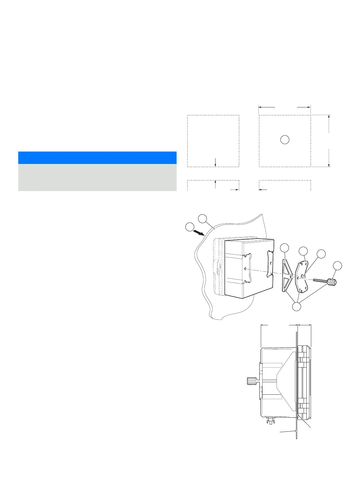
Panel-mounting (optional)
Referring to Figure 6:
1 Cut the correct sized hole in panel A.
2 Insert the transmitter into the panel cut-out B.
3 Screw one panel clamp anchor screw C into the left-hand
bracket D until 10 to 15 mm (0.39 to 0.59 in) of the thread
protrudes from the other side of the bracket and position
one clamp E over the end of the thread.
NOTICE
The correct torque is critical to ensure proper compression
of the panel seal and achieve the IP66/NEMA 4X hosedown
rating.
4 Holding assembly F together, position bracket D into the
left-hand recess on the rear of the transmitter and secure
with bracket securing screw G. Ensure that the plastic
washer remains in the position fitted.
5 Repeat steps 3 and 4 for the right-hand panel clamp
assembly.
6 Torque each panel clamp anchor screw to 0.5 to 0.6 Nm
Figure 6 Panel-mounting the transmitter
A
B
C
D
E
F
A
G
max. thickness 6 (0.236)
Gasket
Panel cut-out dimensions (glands not fitted)
30 (1.2)
73 (2.87)
25.5 (1.00)
138
+1.0
+0.04
(5.43 )
138
+1.0
+0.04
(5.43 )
30
(1.2)
10

 Loading...