AWT420 | UNIVERSAL 4-WIRE, DUAL-INPUT TRANSMITTER | OI/AWT420-EN REV. B
13
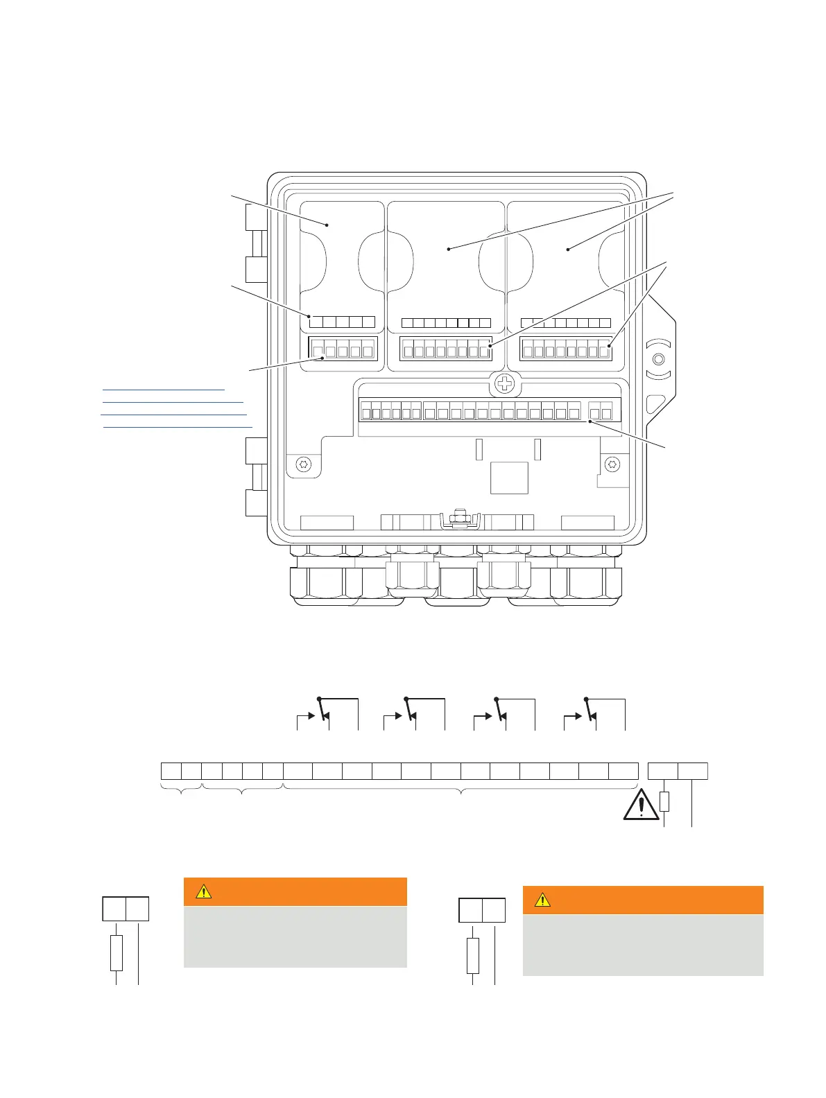
Terminal connections
Figure 9 Electrical connections overview
LN
+–
123456 78910 11 12 13 14 15 16 17 18 LN
Digital I/O
Digital I/O Common
OUT1 +
OUT1 –
OUT2 +
OUT2 –
N/O
N/C
COM
N/O
N/C
COM
N/O
N/C
COM
N/O
N/C
COM
Line
Neutral
12345
OUT3 +
OUT3 –
OUT4 +
GND
OUT4 –
123456 7 8 123456 7 8
Communications Sensor 1Sensor 2
Analog output connections
(see below for communication
module connections)
Analog output/
communications module
PCB slot
refer to separate supplements:
HART COM/AWT420/HART-EN
PROFIBUS COM/AWT420/PROFIBUS-EN
ETHERNET COM/AWT420/ETHERNET-EN
AC
supply
DC
supply
100 to 240 V AC ±10 %, 50/60 Hz
(90 min. to 264 V max. AC, 45/65 Hz)
100 to 240 V AC
15 W max.
Relay connections
Analog
output
connections
I/O
connections
(18 min. to 36 V max.)
Sensor module
connections
Sensor 1 and 2
module
locations
Main board
connections:
see below
Main board connections
WARNING
Bodily injury
Use fuse rating 500 mA (maximum)
WARNING
Bodily injury
Use fuse rating 2.5 A (maximum) type

 Loading...