12 AWT420 | UNIVERSAL 4-WIRE, DUAL-INPUT TRANSMITTER | OI/AWT420-EN REV. B
5 Electrical installation
DANGER
Bodily injury
• Before making any connections, the external protective
earth stud must be connected to the local earth bonding
page 18.
•
device such as a switch or circuit breaker conforming to
local safety standards must be fitted to the final
installation. It must be fitted in close proximity to the
transmitter, within easy reach of the operator and marked
clearly as the isolation device for the transmitter.
• Remove all power from supply, relay, any powered control
circuits and high common mode voltages before
accessing or making any connections. For the mains
power, use 3-core cable rated 3A and for the relay
IEC 60245, or to the National Electrical Code (NEC) for
the US or the Electrical Code for Canada. The terminals
accept cables AWG 24 to 16 (0.2 to 1.5 mm
2
).
• All connections to secondary circuits must have insulation
to required local safety standards. After installation, there
must be no access to live parts, for example, terminals.
Use screened cable for signal inputs and relay
connections. Route signal leads and power cables
separately, preferably in an earthed (grounded) flexible
metal conduit.
USA and Canada only
• Supplied cable glands are an optional extra and provided
communication wiring ONLY. A special cable gland is
supplied with the Ethernet communications option and
should be used only for the Ethernet cable.
• The use of cable glands, cable/flexible cord for
connection of the mains power source to the mains input
and relay contact output terminals is not permitted in the
USA or Canada.
• For connection to mains (the mains input and relay
contact outputs), use only suitably rated field wiring
insulated copper conductors rated min. 300 V, 16 AWG,
90C. Route wires through suitably rated flexible conduits
and fittings.
WARNING
Bodily injury
• If the transmitter is used in a manner not specified by the
Company, the protection provided by the equipment may
be impaired.
• Figure 9, page
13 for fuse details.
• Replacement of the internal battery must be carried out
by an approved technician only.
• The transmitter conforms to Installation Category II of
IEC 61010.
• All equipment connected to the transmitter’s terminals
must comply with local safety standards (IEC 60950,
EN61010-1).
•
interface connectors must be connected to Safety Extra
Low Voltage (SELV) circuits.
Earth bonding
WARNING
Before making any electrical connections:
• The external protective earth stud (see Figure 11, page
17) must be connected to the local earth bonding point
using suitably sized ground cable. To connect to the
protective earth stud, use a closed M4 cable lug.
• Never connect the protective earth with an end sleeve or
an open cable lug.
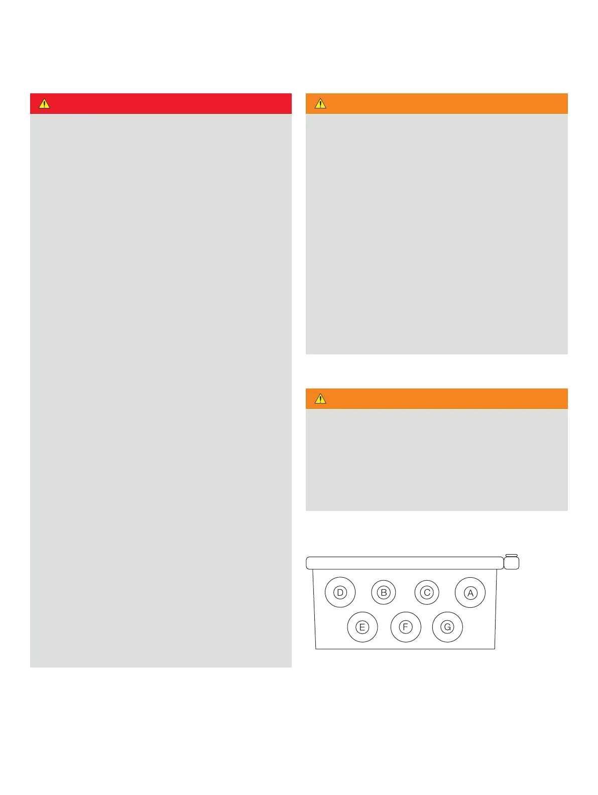
Cable entries
A E
B F
C G
D
Figure 8 Cable entries

 Loading...