18 AW T420 | UNIVERSAL 4-WIRE, DUAL-INPUT TRANSMITTER | OI/AWT420-EN REV. B
…5 Electrical installation
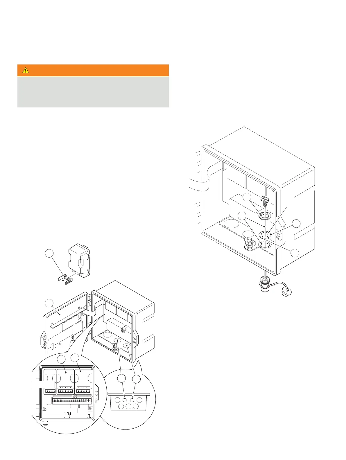
Fitting the EZLink modules
WARNING
Bodily injury
• Up to 240 V AC may be present. Isolate the power supply
before removing the opening the transmitter door.
Referring to Figure 12:
1 Remove connector block cradle A from EZLink module(s)
and retain for connection.
2 Unlock and open transmitter door B.
3 Fit EZLink modules as follows:
a if one EZLink module is used, push-fit it into location C
(sensor 1).
Note. When fitting the cable assembly, the EZLink
connector for sensor 1 passes through cable entry D.
b if two EZLink modules are used, push-fit sensor 1 module
into location C and sensor 2 module into location E.
Note. When fitting the cable assemblies, the EZLink
connector for sensor 1 passes through cable entry D and
the EZLink connector for sensor 2 passes through cable
entry F.
Figure 12 EZLink module positions and EZLink cable entries
Referring to Figure 13:
4 Pass EZLink connector cable G through the correct cable
5 Pass thread alignment washer H over EZLink connector
cable G, ensuring alignment tab I is orientated correctly.
6 Pass thread back nut J over EZLink correctly connector
cable G.
Figure 13 Preparing EZLink connector cable fixings
B
A
D
F
D
F
C
E
GG
H
I
J