EasyManua.ls Logo

ABB IRB 6700 Series User Manual

ABB IRB 6700 Series
846 pages
To Next Page IconTo Next Page
To Previous Page IconTo Previous Page
Page #50 background imageLoading...
Page #50 background image
WARNING
The robot installation is restricted to the mounting options given in following load
table(s).
Floor mounted
Max. load (emergency stop)Endurance load (in operation)Force
±19.8 kN
i
/ ±21.8 kN
ii
±7.4 kN
i
/ ±8.7 kN
ii
Force xy
14.6 ±15.7 kN
i
/ 18.0 ±17.4 kN
ii
14.6 ±4.5 kN
i
/ 18.0 ±5.4 kN
ii
Force z
±37.1 kNm
i
/ ±45.3 kNm
ii
±21.0 kNm
i
/ ±24.9 kNm
ii
Torque xy
±11.4 kNm
i
/ ±15.5 kNm
ii
±5.0 kNm
i
/ ±6.5 kNm
ii
Torque z
i
Valid for IRB 6700-235, -205, -175, -150, -200, -155.
ii
Valid for IRB 6700-300, -245.
Requirements, foundation
The table shows the requirements for the foundation where the weight of the
installed robot is included:
NoteValueRequirement
Flat foundations give better repeatability of the
resolver calibration compared to original settings
on delivery from ABB.
0.3 mmFlatness of foundation
surface
The value for levelness aims at the circumstance
of the anchoring points in the robot base.
In order to compensate for an uneven surface,
the robot can be recalibrated during installation.
If resolver/encoder calibration is changed this
will influence the absolute accuracy.
0°Maximum tilt
The value is recommended for optimal perform-
ance.
22 Hz
Note
It may affect the
manipulator life-
time to have a
lower resonance
frequency than
recommended.
Minimum resonance
frequency
Due to foundation stiffness, consider robot mass
including equipment.
i
For information about compensating for founda-
tion flexibility, see Application manual - Control-
ler software IRC5, section Motion Process Mode.
i
The minimum resonance frequency given should be interpreted as the frequency of the robot
mass/inertia, robot assumed stiff, when a foundation translational/torsional elasticity is added, i.e.,
the stiffness of the pedestal where the robot is mounted. The minimum resonance frequency should
not be interpreted as the resonance frequency of the building, floor etc. For example, if the equivalent
mass of the floor is very high, it will not affect robot movement, even if the frequency is well below
the stated 25 Hz. The robot should be mounted as rigid as possibly to the floor.
Disturbances from other machinery will affect the robot and the tool accuracy. The robot has
resonance frequencies in the region 10 – 20 Hz and disturbances in this region will be amplified,
although somewhat damped by the servo control. This might be a problem, depending on the
requirements from the applications. If this is a problem, the robot needs to be isolated from the
environment.
Continues on next page
50 Product manual - IRB 6700
3HAC044266-001 Revision: N
© Copyright 2013 - 2018 ABB. All rights reserved.
2 Installation and commissioning
2.2.1 Pre-installation procedure
Continued

Table of Contents

Question and Answer IconNeed help?

Do you have a question about the ABB IRB 6700 Series and is the answer not in the manual?
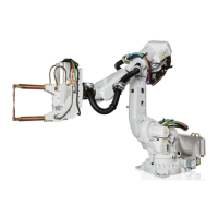
ABB IRB 6700 Series Specifications

General IconGeneral
Payload150-300 kg
Reach2.60-3.20 m
Number of Axes6
Protection RatingIP67
ControllerIRC5
ProtectionFoundry Plus 2
MountingFloor

Summary

1 Safety

1.1 General safety information

Covers general safety aspects and specific information on avoiding personal injuries and product damage.

1.3 Safety risks

Details safety risks during installation, service, and operational disturbances.

1.4 Safety signals and symbols

Explains danger levels, safety signals, and symbols used in the manual and on product labels.

2 Installation and commissioning

2.1 Introduction

Overview of assembly instructions and technical data for installing the IRB 6700.

2.2 Unpacking

Covers unpacking and pre-installation procedures, including storage and operating conditions.

2.4 On-site installation

Provides brief installation steps, including base plate and manipulator securing.

2.6 Electrical connections

Details robot cabling and connection points for power, signals, and fan cables.

3 Maintenance

3.1 Introduction

Overview of maintenance activities, schedule, and procedures for the IRB 6700.

3.2 Maintenance schedule and expected component life

Specifies maintenance intervals, schedules, and expected component lifespan.

3.3 Inspection activities

Details inspection procedures for motor seals, oil levels, cable harnesses, and other components.

3.4 Replacement/changing activities

Covers procedures for replacing components like gearboxes, batteries, and lubricants.

4 Repair

4.1 Introduction

Introduction to repair activities, required equipment, and safety information.

4.2 General procedures

Details general repair procedures like leak-down tests and mounting instructions.

4.3 Lifting associated procedures

Provides procedures for attaching lifting accessories for safe lifting of robot parts.

4.5 Upper and lower arms

Covers replacement of upper and lower arm components, including the wrist.

4.7 Motors

Details procedures for replacing motors for various axes (axis-1, axis-2, etc.).

4.8 Gearboxes

Provides procedures for replacing gearboxes for different axes (axis-1, axis-2, etc.).

5 Calibration

5.1 Introduction to calibration

General information about calibration methods and terminology.

5.3 Updating revolution counters

Describes how to update revolution counters for rough calibration of manipulator axes.

5.4 Calibrating with Axis Calibration method

Detailed description of the Axis Calibration method, tools, and procedures.

6 Decommissioning

6.1 Environmental information

Information on product disposal, hazardous materials, and oil/grease recycling.

6.2 Scrapping of robot

Important safety precautions for robot disassembly and scrapping.

6.3 Decommissioning of balancing device

Details on safely decommissioning the balancing device due to stored energy.

7 Robot description

7.1 Type A vs type B motors

Identifies motor types visually and by article number, including interchangeability.

8 Reference information

8.2 Applicable standards

Lists relevant EN ISO and European standards applicable to the product.

8.4 Screw joints

Provides guidance on tightening screw joints, including torque values and lubrication.

8.6 Standard toolkit

Lists standard tools required for service, repair, and installation activities.

8.7 Special tools

Lists special tools required for specific activities, with article numbers.

9 Spare parts

9.1 Spare part lists and illustrations

Information on where to find spare parts lists and exploded views.

10 Circuit diagrams

10.1 Circuit diagrams

Information on where to find circuit diagrams for controllers and robots.

Related product manuals