2 Installation and commissioning
2.6.5. Installation of position switches (option)
1293HAC022033-001 Revision: K
© Copyright 2004-2011 ABB. All rights reserved.
Installation of cable harness for position switches and fans
The procedure below details how to fit the complete cable harness for position switches and
cooling fans to the robot.
R3.FAN3 Connected to the fan of axis 3
R2.SW2 Connected to the position switch of axis 2
R2.SW3 Connected to the position switch of axis 3
Action Note
1. Move the robot to its calibration position.
2.
DANGER!
Turn off all electric power, hydraulic and
pneumatic pressure supplies to the robot!
Turn off all electric power and hydraulic but
not the air pressure to the gearboxes,
motors and SMB.
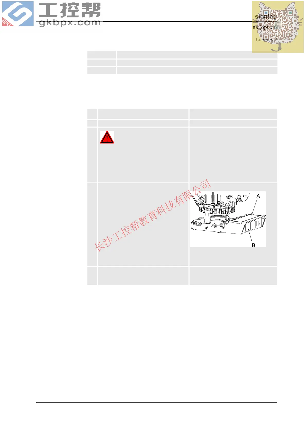
3. Remove the rear cover (A) from the robot
base and replace the protection (B) with a
plate for customer connections (if not
already mounted).
xx0500002306
Art. no. for the plate is specified in
Required equipment on page 122.
4. Run the cabling through the base and frame
of the robot, up beneath the balancing
device.
Continued
Continues on next page
 Loading...