The protection relay with a standardized configuration is delivered from the factory
with default settings and parameters. The end-user flexibility for incoming, outgoing
and internal signal designation within the protection relay enables this configuration
to be further adapted to different primary circuit layouts and the related functionality
needs by modifying the internal functionality using PCM600.
3.6.2 Functions
REMARKS
Optional
function
No. of
instances
Alternative
function to be
defined when
ordering
Io/Uo
Calculated
value
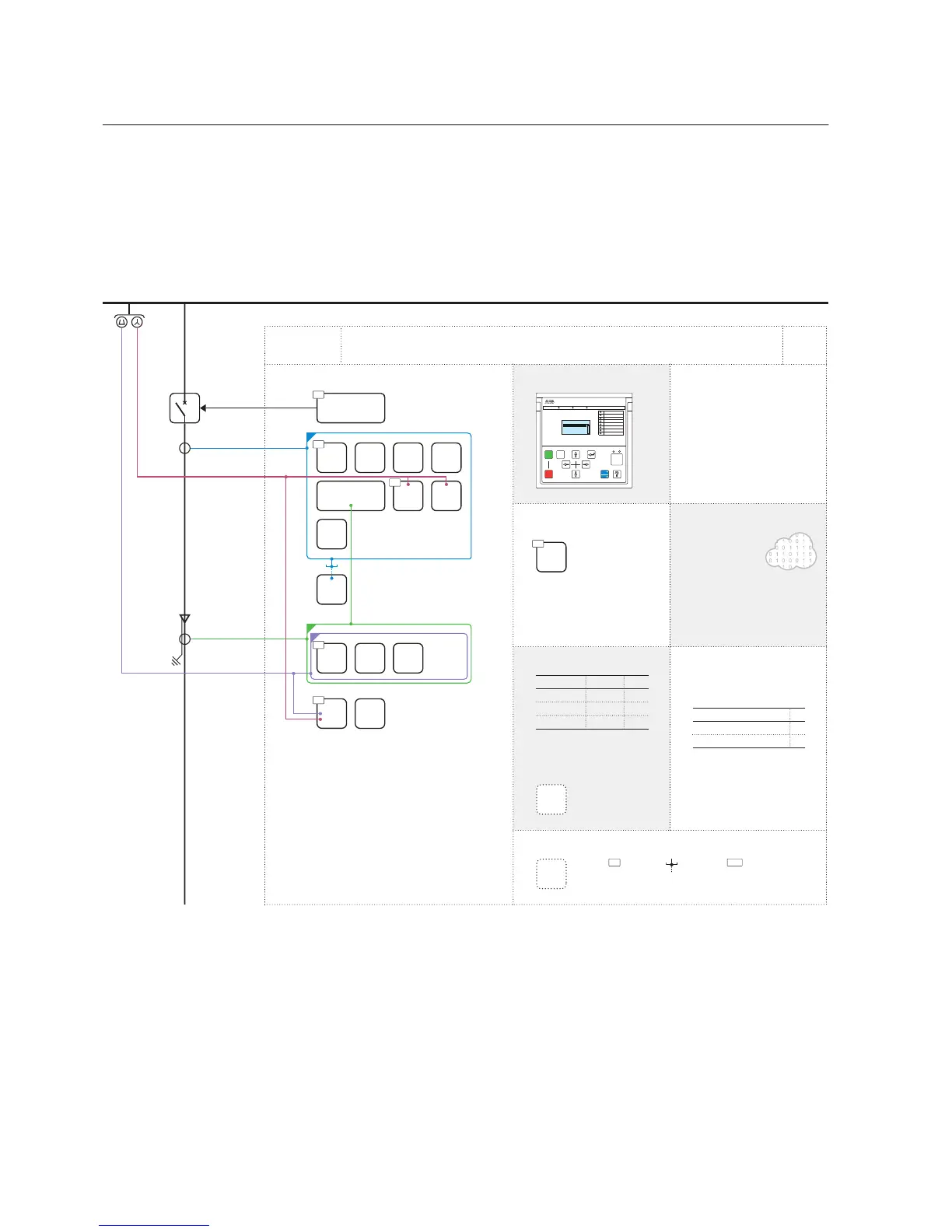
CONDITION MONITORING
AND SUPERVISION
CONTROL AND INDICATION
1)
MEASUREMENT
- I, U, Io, Uo, P, E, f
- Limit value supervision
- Symmetrical components
FEEDER PROTECTION RELAY STANDARD
CONFIGURATION
LOCAL HMI
C
COMMUNICATION
Protocols:
IEC 61850-8-1
Modbus®
Interfaces:
Ethernet: TX (RJ-45), FX (LC)
Serial: RS-485
Redundant protocols:
HSR
PRP
RSTP
4
4
Analog interface types
1)
Current transformer
Voltage transformer
1)
Conventional transformer inputs
Object Ctrl
2)
Ind
3)
CB
DC
ES
1 -
- -
- -
1)
Check availability of binary inputs/outputs
from technical documentation
2)
Control and indication function for
primary object
3)
Status indication function for
primary object
Master Trip
Lockout relay
94/86
PROTECTION
3I
Uo
Uo
Io
ALSO AVAILABLE
- Disturbance and fault recorders
- Event log and recorded data
- Local/Remote push button on LHMI
- Self-supervision
- Time synchronization: IEEE 1588 v2,
SNTP, IRIG-B
- User management
- Web-HMI
R
L
ESC
I
O
A
Control
Events
Measurements
Disturbance records
GUID-F966F334-E227-496D-9566-CF55952CC985 V1 EN
Figure 105: Functionality overview for configuration C
Section 3 1MRS757456 D
REF611 standardized configurations
122 REF611
Application Manual
 Loading...


