5.1.1.4 Phase voltage
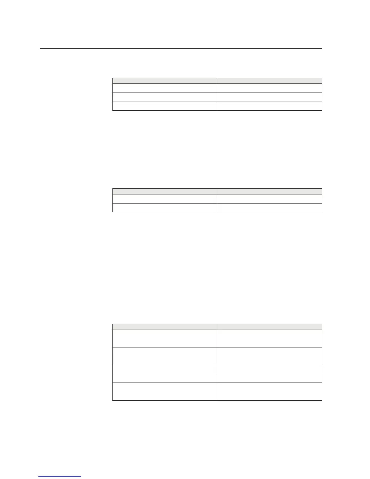
Table 31: Phase voltage inputs included in configuration C
Terminal
Description
X130:11-12 U1
X130:13-14 U2
X130:15-16 U3
5.1.2 Auxiliary supply voltage input
The auxiliary voltage of the protection relay is connected to terminals X100:1-2. At
DC supply, the positive lead is connected to terminal X100:1. The permitted auxiliary
voltage range (AC/DC or DC) is marked on the top of the LHMI of the protection
relay.
Table 32: Auxiliary voltage supply
Terminal Description
X100:1 + Input
X100:2 - Input
5.1.3 Binary inputs
The binary inputs can be used, for example, to generate a blocking signal, to unlatch
output contacts, to trigger the disturbance recorder or for remote control of protection
relay settings.
Terminals X120:1-4 are binary input terminals. In the protection relay variant B, there
are additional binary inputs X120:5-6 included. Optional BIO-module BIO0006 for
slot X130 can be included at the time of order.
Binary inputs of slot X120 are available with configurations A and B.
Table 33: Binary input terminals X120-1...6
Terminal
Description
X120:1 BI1, +
X120:2 BI1, -
X120:3 BI2, +
X120:2 BI2, -
X120:4 BI3, +
X120:2 BI3, -
X120:5 BI4, +
X120:6 BI4, -
Section 5 1MRS757456 D
Protection relay's physical connections
174 REF611
Application Manual
 Loading...


