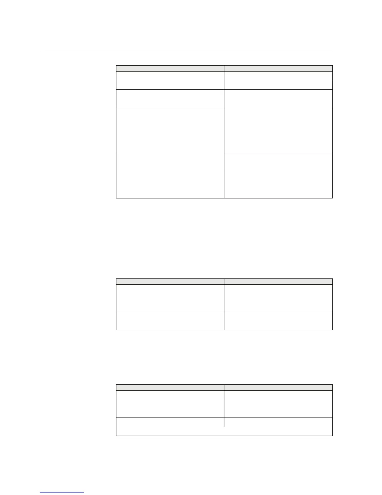
Table 36: Output contacts
Terminal Description
X100:6 PO1, NO
X100:7 PO1, NO
X100:8 PO2, NO
X100:9 PO2, NO
X100:15 PO3, NO (TCS resistor)
X100:16 PO3, NO
X100:17 PO3, NO
X100:18 PO3 (TCS1 input), NO
X100:19 PO3 (TCS1 input), NO
X100:20 PO4, NO (TCS resistor)
X100:21 PO4, NO
X100:22 PO4, NO
X100:23 PO4 (TCS2 input), NO
X100:24 PO4 (TCS2 input), NO
5.2.2 Outputs for signalling
Output contacts SO1 and SO2 in slot X100 or SO1, SO2 and SO3 in slot X130
(optional) can be used for signalling on start and tripping of the protection relay. On
delivery from the factory, the start and alarm signals from all the protection stages are
routed to signalling outputs.
Table 37: Output contacts X100:10...14
Terminal
Description
X100:10 SO1, common
X100:11 SO1, NC
X100:12 SO1, NO
X100:13 SO2, NO
X100:14 SO2, NO
Output contacts of slot X130 are available in the optional BIO module (BIO0006).
Output contacts of slot X130 are optional for configurations A and B.
Table 38: Output contacts X130:10...18
Terminal
Description
X130:10 SO1, common
X130:11 SO1, NO
X130:12 SO1, NC
X130:13 SO2, common
Table continues on next page
Section 5 1MRS757456 D
Protection relay's physical connections
176 REF611
Application Manual
 Loading...


