REMARKS
Optional
function
No. of
instances
Alternative
function to be
defined when
ordering
Io/Uo
Calculated
value
CONDITION MONITORING
AND SUPERVISION
CONTROL AND INDICATION
1)
MEASUREMENT
- I, Io, Uo
- Limit value supervision
- Symmetrical components
FEEDER PROTECTION RELAY STANDARD
CONFIGURATION
LOCAL HMI
REF611
A
COMMUNICATION
Protocols:
IEC 61850-8-1
Modbus®
Interfaces:
Ethernet: TX (RJ-45), FX (LC)
Serial: RS-485
Redundant protocols:
HSR
PRP
RSTP
4
1
Analog interface types
1)
Current transformer
Voltage transformer
1)
Conventional transformer inputs
Object Ctrl
2)
Ind
3)
CB
DC
ES
1 -
- -
- -
1)
Check availability of binary inputs/outputs
from technical documentation
2)
Control and indication function for
primary object
3)
Status indication function for
primary object
Master Trip
Lockout relay
94/86
PROTECTION
3I
Uo
Uo
Io
ALSO AVAILABLE
- Disturbance and fault recorders
- Event log and recorded data
- Local/Remote push button on LHMI
- Self-supervision
- Time synchronization: IEEE 1588 v2,
SNTP, IRIG-B
- User management
- Web-HMI
R
L
ESC
I
O
A
Control
Events
Measurements
Disturbance records
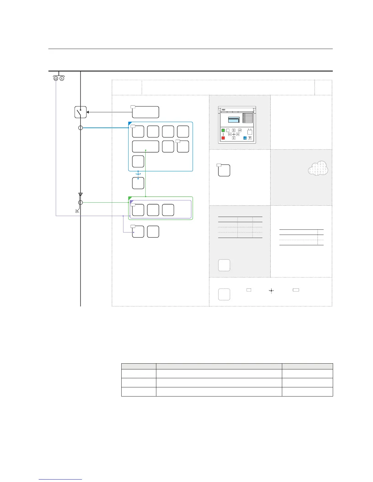
GUID-22599DC2-ADFC-482B-BB9A-985109CE4F9D V1 EN
Figure 15: Functionality overview for configuration A
3.4.2.1 Default I/O connections
Table 11: Default connections for binary inputs
Binary input
Description Connector pins
X120-BI1 Blocking of overcurrent instantaneous stage X120:1-2
X120-BI2 Circuit breaker closed position indication X120:3,2
X120-BI3 Circuit breaker open position indication X120:4,2
1MRS757456 D Section 3
REF611 standardized configurations
REF611 35
Application Manual
 Loading...


