2.2 Operation functionality
2.2.1 Optional functions
• Autoreclosing
• Modbus TCP/IP or RTU/ASCII
• IEEE 1588 time v2 synchronization
• High-availability seamless redundancy protocol (HSR)
• Parallel redundancy protocol (PRP)
2.3 Physical hardware
The protection relay consists of two main parts: plug-in unit and case. The content
depends on the ordered functionality.
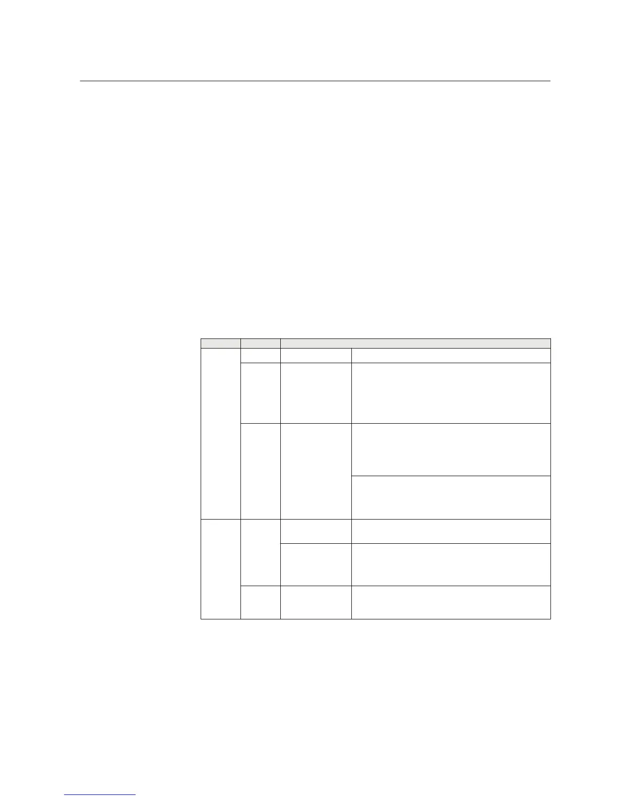
Table 2: Plug-in unit and case
Main unit Slot ID Content options
Plug-in
unit
- HMI Small (4 lines, 16 characters)
X100 Auxiliary
power/BO module
48...250 V DC/100...240 V AC; or 24...60 V DC
2 normally-open PO contacts
1 change-over SO contact
1 normally-open SO contact
2 double-pole PO contacts with TCS
1 dedicated internal fault output contact
X120
AI/BI module Only with configuration A:
3 phase current inputs (1/5 A)
1 residual current input (1/5 A or 0.2/1 A)
1)
1 residual voltage input (60...120 V)
3 binary inputs
Only with configurations B and C:
3 phase current inputs (1/5 A)
1 residual current input (1/5 A or 0.2/1 A)
1)
4 binary inputs
Case
X130 Optional BI/O
module
Optional for configurations B and C:
6 binary inputs 3 SO contacts
AI/BI module Only with configuration C:
3 phase voltage inputs (60...210 V)
1 residual voltage input (60...210 V)
4 binary inputs
X000
Optional
communication
module
See technical manual for details about different type of
communication modules.
1) The 0.2/1 A input is normally used in applications requiring sensitive earth-fault protection and featuring
core-balance current transformers.
1MRS757456 D Section 2
REF611 overview
REF611 13
Application Manual
 Loading...


