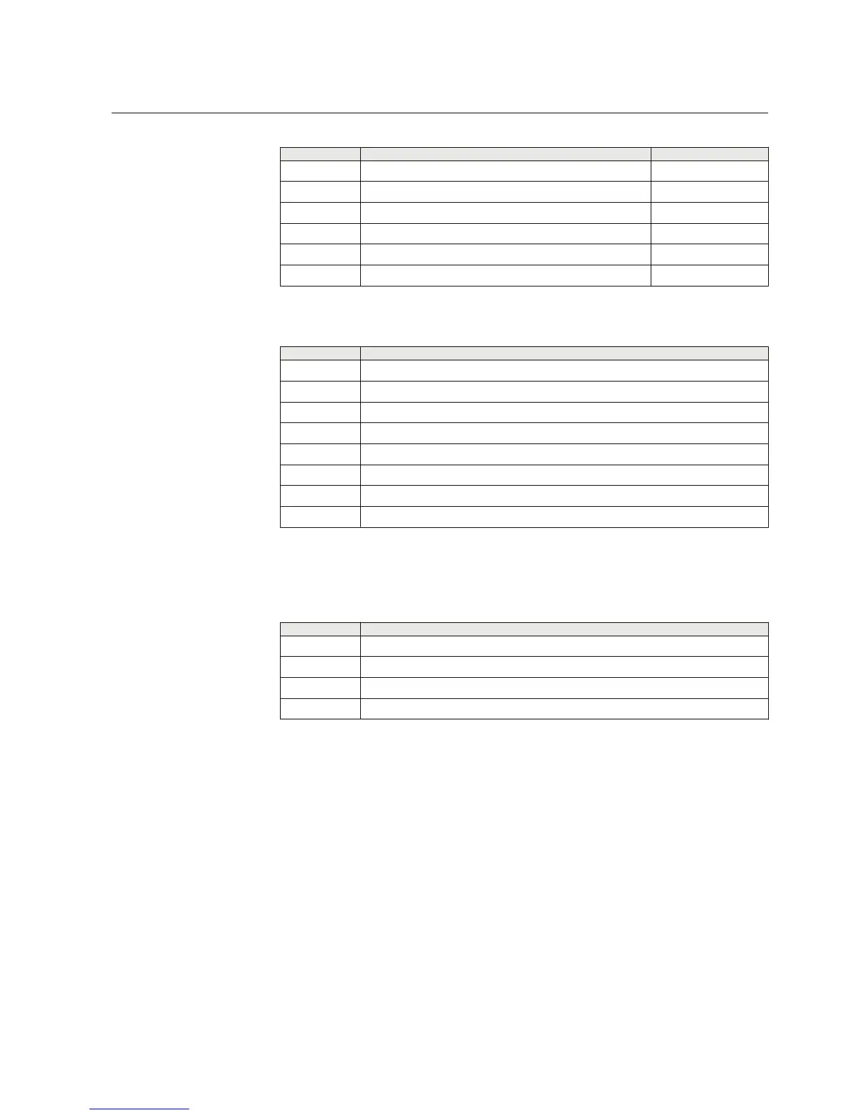
Table 17: Default connections for binary outputs
Binary input Description Connector pins
X100-PO1 Close circuit breaker X100:6-7
X100-PO2 Circuit breaker failure protection trip to upstream breaker X100:8-9
X100-PO3 Open circuit breaker/trip coil 1 X100:15-19
X100-PO4 Open circuit breaker/trip coil 2 X100:20-24
X100-SO1 General start indication X100:10-12
X100-SO2 General operate indication X100:13-15
Table 18: Default connections for LEDs
LED Description
1 Non-directional overcurrent operate
2 Earth fault operate
3 Negative-sequence overcurrent/phase discontinuity operate
4 Thermal overload alarm
5 Autoreclose in progress
6 Disturbance recorder triggered
7 Trip circuit supervision alarm
8 Circuit-breaker failure operate
3.5.2.2 Predefined disturbance recorder connections
Table 19: Predefined analog channel setup
Channel
Description
1 IL1
2 IL2
3 IL3
4 Io
Additionally, all the digital inputs that are connected by default are also enabled with
the setting. Default triggering settings are selected depending on the connected input
signal type. Typically all protection START signals are selected to trigger the
disturbance recorded by default.
3.5.3 Functional diagrams
The functional diagrams describe the default input, output, programmable LED,
switch group and function-to-function connections. The default connections can be
viewed and changed with switch groups in PCM600, LHMI and WHMI according to
the application requirements.
1MRS757456 D Section 3
REF611 standardized configurations
REF611 83
Application Manual
 Loading...


