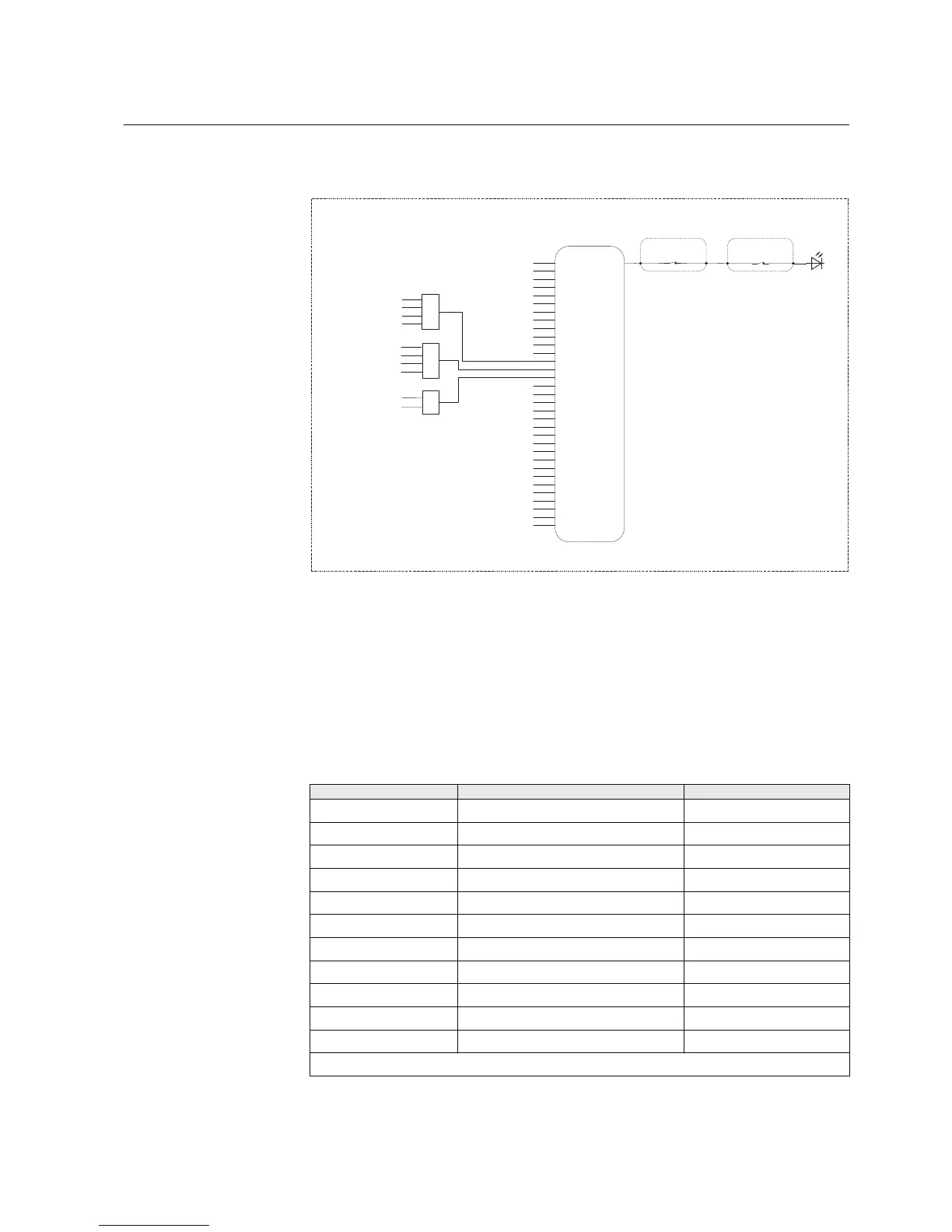
GUID-D5C64B52-5763-48FA-AC6A-14257698FEBC V3 EN
Figure 67: Disturbance recorder
All start and operate signals from the protection stages are routed to trigger the
disturbance recorder or alternatively only to be recorded by the disturbance recorder
depending on the parameter settings. Additionally, the selected autoreclose output
signals and the three binary inputs from X120 are also connected. The active setting
group is also to be recorded via SG_1_ACT to SG_6_ACT. The disturbance recorder
triggered signal indication is connected to LED 6.
Table 20: Disturbance recorder binary channel default value
Channel number
Channel id text Level trigger mode
Binary channel 1 PHLPTOC1_START 1=positive or rising
Binary channel 2 PHHPTOC1_START 1=positive or rising
Binary channel 3 PHHPTOC2_START 1=positive or rising
Binary channel 4 PHIPTOC1_START 1=positive or rising
Binary channel 5 EFLPTOC1_START 1=positive or rising
Binary channel 6 EFLPTOC2_START 1=positive or rising
Binary channel 7 EFHPTOC1_START 1=positive or rising
Binary channel 8 EFIPTOC1_START 1=positive or rising
Binary channel 9 NSPTOC1_START 1=positive or rising
Binary channel 10 NSPTOC2_START 1=positive or rising
Binary channel 11 PDNSPTOC1_START 1=positive or rising
Table continues on next page
1MRS757456 D Section 3
REF611 standardized configurations
REF611 89
Application Manual
 Loading...


