ABB | SACE Emax 2
180 | © 2017 ABB | 1SDH001330R0002 - ECN000058721 Rev. A Electronic accessories | 3 - Ekip Measuring modules
Measurements
The following table lists the measurement accuracy for the modules:
Quantity Range Accuracy
Phase-to-phase voltage
(1)
100…1150 V AC ± 0.5 % @ 45…66 Hz
Frequency
(2)
30…80 Hz ± 0.1 %
(3)
(1)
With phase-to-phase voltage V greater than 690 V AC rated voltage (maximum 760 V AC), in the presence of
external sockets and an isolation transformer.
(2)
The measurement of the frequency is available with a a phase-to-phase voltage value ≥ 36 V AC, and is
unavailable with a phase-to-phase voltage value ≤ 32 V AC.
(3)
In the absence of harmonic distortion.
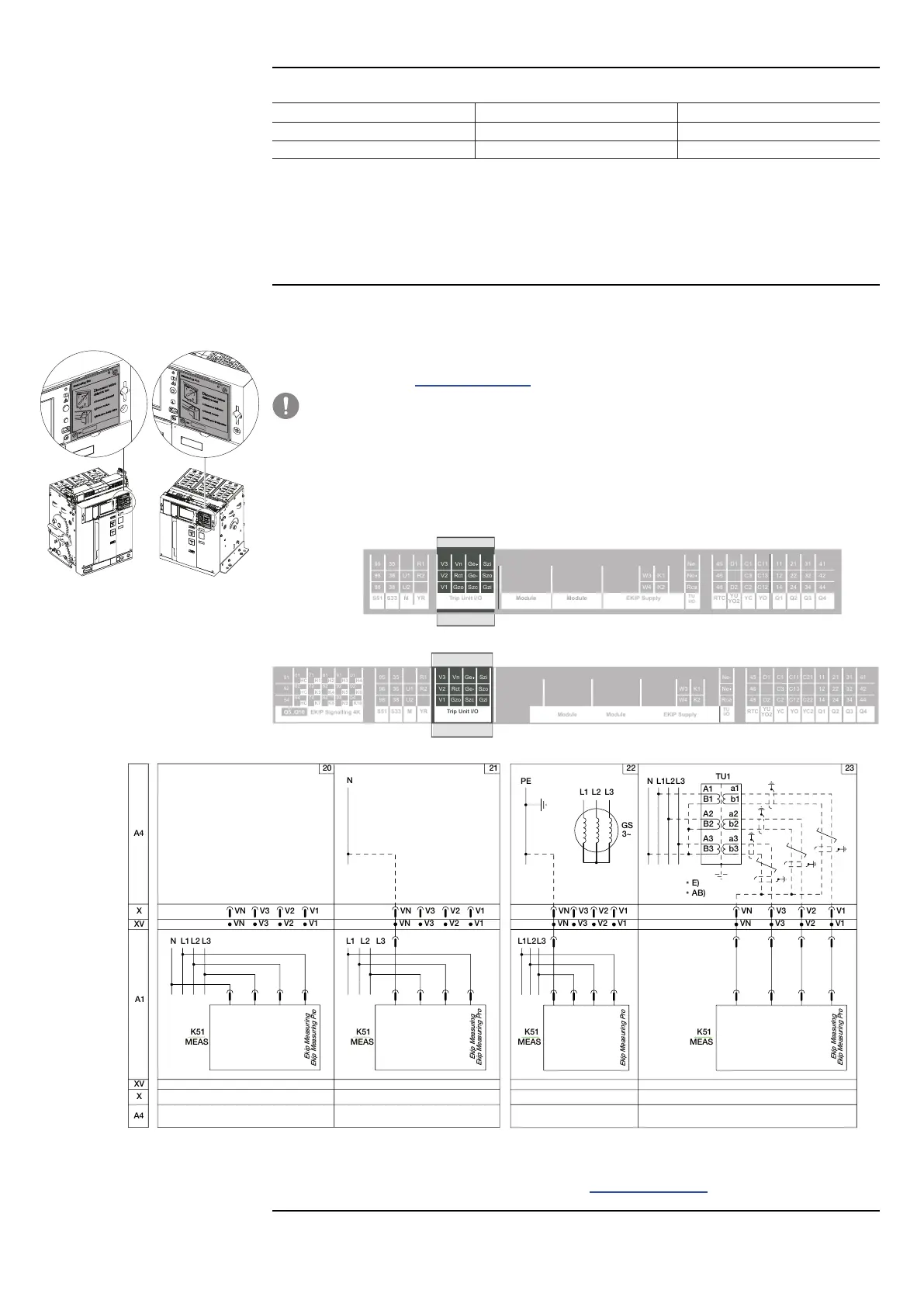
Connections
The modules must be mounted directly on the Mainboard, to the right of the trip unit. In parallel they are
connected to a connector, to which the phase and neutral voltages arrive either on the internal contacts of
the circuit-breaker, or on the external sockets.
Information on the assembly is available on the website http://www.abb.com/abblibrary/DownloadCenter/, in
particular in the kit sheet 1SDH001000r0505.
IMPORTANT: in the case of dielectric tests, you need to disconnect the modules as
illustrated in the assembly diagram, and to disconnect the external sockets from the
terminal box. It is not necessary to remove the modules.
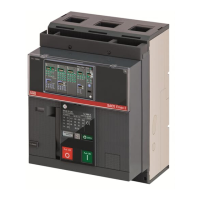
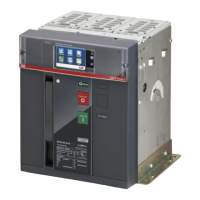
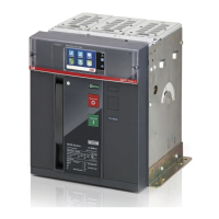
An example with an E2.2 circuit-breaker in fixed and withdrawable versions is provided to the side.
The following is a view of the terminal box of E1.2 and E2.2-E4.2-E6.2 circuit-breakers with the relevant wiring
diagram:
R2
R1
U2
U1
38
36
35
98
96
95
YRMS33S51
YO
EKIP SupplyTrip Unit I/O
Ge-
Ge
Szc
K2
K1
W4
W3
Q4Q3Q2Q1YC
YU
YO2
RTC
I/O
TU
44
42
41
34
32
31
24
22
21
14
12
11
C12
C13
C11
C2
C3
C1
D2
D1
48
46
45
Ne
Rca
Ne-
Gzi
Szo
Szi
Gzo
Rct
Vn
V1
V2
V3
Module Module
YO
01
H4
02
K5
04
K10K9
94
92
H3
9181
H2
82
K4
K8
8474
K7
K3
H1
72
7161
HC
62
HC
64
54
52
51
Trip Unit I/O
HC
K6
Ge-
Ge
Szc
K2
K1
W4
W3
R2
R1
Q4Q3Q2Q1YC2YC
YU
YO2
RTC
I/O
TU
44
42
41
34
32
31
24
22
21
14
12
11
C22
C21
C12
C13
C11
C2
C3
C1
D2
D1
48
46
45
Ne
Rca
Ne-
Gzi
Szo
Szi
Gzo
Rct
Vn
V1
V2
V3
U2
U1
38
36
35
98
96
95
YRMS33S51
EKIP Signalling 4KQ5..Q10
Module Module Module
EKIP Supply
V1
V1
V2
V2
V3
V3
VN
VN
L3L2L1N
XV
XV
A4
X
A1
X
A4
L1 L2 L3
VN
VN
V3
V3
V2
V2
V1
V1
N
Ekip Measuring Pro
Ekip Measuring
Ekip Measuring Pro
Ekip Measuring
MEAS
K51 K51
MEAS
L3L2L1N
A3
B3
a3
b3
A2
B2
a2
b2
TU1
A1
B1
a1
b1
Ekip Measuring Pro
Ekip Measuring
MEAS
K51
VN
VN
V3
V3
V2
V2
V1
V1
E)
*
Ekip Measuring Pr
o
V1
V1
V2
V2
V3
V3
VN
VN
L3L2L1
K51
MEAS
L3L1 L2
GS
PE
3~
AB)
*
Diagrams 20 - 21 - 22 - 23
Further information is available on page 174, or on the website http://www.abb.com/abblibrary/
DownloadCenter/, where the wiring diagram is available 1SDm000091r0001.

 Loading...