ABB | SACE Emax 2
Electronic accessories | 10 - Ekip Com Modbus TCP modules221 | © 2017 ABB | 1SDH001330R0002 - ECN000058721 Rev. A
Continued from the previous page
Further details are given in document 1SDH001140r0001 (Communication System
Interface for Emax 2), sections Status Global 1 [dlog], Status Accessories 1 and
Status Accessories 2.
The modules are always supplied with Ekip AUP and Ekip RTC contacts (see the chapter "16 - Other
accessories" on page 244).
Compatibility and power supply
The modules can be installed combined with Ekip Touch, Hi-Touch, G Touch, and G Hi-Touch trip units, and
require the presence of an Ekip Supply module in the first slot of the circuit-breaker terminal box.
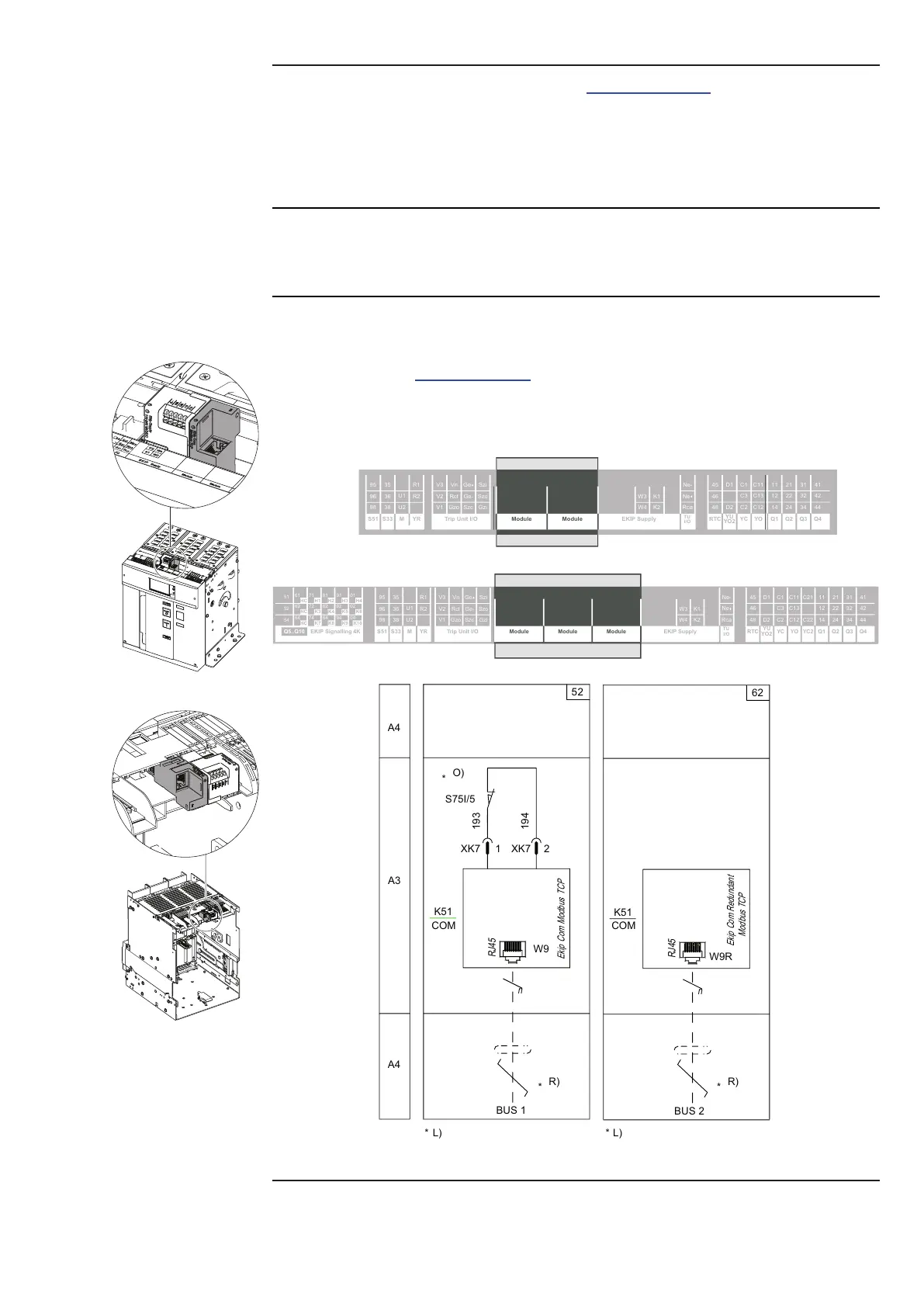
Connections
The modules must be mounted on the terminal box of the circuit-breaker or of the fixed part of the withdrawable
circuit-breaker, in the first free slot after the Ekip Supply module.
Information on the assembly is available on the website http://www.abb.com/abblibrary/DownloadCenter/, in
particular in the kit sheet 1SDH001000r0514.
An example with an E2.2 circuit-breaker in fixed and withdrawable versions is provided to the side.
The following is a view of the terminal box of E1.2 and E2.2/E4.2/E6.2 circuit-breakers with the relevant wiring
diagram:
R2
R1
U2
U1
38
36
35
98
96
95
YRMS33S51
YO
EKIP SupplyTrip Unit I/O
Ge-
Ge
Szc
K2
K1
W4
W3
Q4Q3Q2Q1YC
YU
YO2
RTC
I/O
TU
44
42
41
34
32
31
24
22
21
14
12
11
C12
C13
C11
C2
C3
C1
D2
D1
48
46
45
Ne
Rca
Ne-
Gzi
Szo
Szi
Gzo
Rct
Vn
V1
V2
V3
Module Module
YO
01
H4
02
K5
04
K10K9
94
92
H3
9181
H2
82
K4
K8
8474
K7
K3
H1
72
7161
HC
62
64
54
52
51
EKIP SupplyModuleTrip Unit I/O
HC
K6
Ge-
Ge
Szc
K2
K1
W4
W3
R2
R1
Q4Q3Q2Q1YC2YC
YU
YO2
RTC
I/O
TU
44
42
41
34
32
31
24
22
21
14
12
11
C22
C21
C12
C13
C11
C2
C3
C1
D2
D1
48
46
45
Ne
Rca
Ne-
Gzi
Szo
Szi
Gzo
Rct
Vn
V1
V2
V3
U2
U1
38
36
35
98
96
95
YRMS33S51
EKIP Signalling 4KQ5..Q10
Module Module
HC
A4
A3
A4
52
194
XK7 XK7
1 2
193
S75I/5
W9
RJ45
BUS 1
Ekip
Com Modbus
TCP
n
COM
K51
O)
*
n
Ekip Com Redundant
Modbus TCP
BUS 2
RJ45
W9R
62
K51
COM
R)
*
R)
*
Diagrams 52 - 62
Continued on the next page

 Loading...