 Loading...
Do you have a question about the ABB SACE Emax E1.2 and is the answer not in the manual?
| Brand | ABB |
|---|---|
| Model | SACE Emax E1.2 |
| Category | Circuit breakers |
| Language | English |
Introduction to the SACE Emax 2 series of low voltage air circuit-breakers.
Details compliance with international standards and EC directives.
Provides criteria for selecting Emax 2 circuit-breakers, including device, standard, and mechanical characteristics.
Details electrical specifications such as rated voltage, uninterrupted current, and short-circuit breaking capacity.
Lists basic and additional protection functions available for Ekip DIP, Ekip Touch, and Ekip LCD trip units.
Lists electrical signalling accessories like AUX contacts and remote resetting coils.
Lists service trip units such as opening and closing coils.
Describes the motor operator accessory.
Lists various electronic accessories like Ekip Measuring, Ekip Signalling, Ekip Supply, and Ekip COM modules.
Describes different types of selectivity including current-based, time, time-current, energy, and zone selectivity.
References additional documentation for detailed information on selectivity.
Lists available software programs like e-Design, DOC, CAT, Curves, DOCSolar, and OTC for design and analysis.
Describes Front CAD software for switchgear design with AutoCAD libraries.
ABB SACE software for interfacing with low voltage circuit-breakers.
Main features of SACE Emax 2 circuit-breakers.
Origin and evolution of ABB air circuit-breakers for low voltage applications.
General overview of Emax 2 features for consultants.
General overview of Emax 2 features for switchgear engineers.
Introduction to the Ekip Link switchgear control system.
Introduction to the Power Controller load management system.
General features for generator protections with Emax 2 trip units.
Advantages and details of migrating from New Emax to Emax 2 circuit-breakers.
Information on generator protections.
Details on the Power Controller function.
Overview of IEC 61850 communication modules.
Introduction to the Network Analyzer system.
Emax 2 general catalogue.
Introduces Ekip trip units, their families, functionality, and interface types.
Lists basic protections available for Ekip DIP trip units.
Lists protections available for Ekip Touch trip units.
Lists protections available with Ekip Measuring Pro.
Lists protections available for Ekip Hi-Touch trip units.
Lists protections available for Ekip G Touch trip units.
Lists protections available for Ekip G Hi-Touch trip units.
Details measurements available for Ekip Dip trip units.
Details measurements available for Ekip Touch trip units.
Details measurements available with Ekip Measuring modules.
Details measurements available for Hi-Touch trip units.
Describes test and self-diagnosis functions for Ekip Dip.
Describes test, self-diagnosis, and Power Controller functions for Ekip Touch.
Lists modules connecting directly to the trip unit, e.g., Ekip Measuring and Ekip Signalling.
Lists modules for the terminal box, including Ekip Supply, Ekip Com, and Ekip Link.
Lists modules external to the circuit-breaker, e.g., Ekip Multimeter and Ekip Signalling 10K.
Lists modules for temporary power supply and communication, e.g., Ekip TT and Ekip T&P.
Describes the operator interface of the Ekip Dip protection trip unit, including components and LEDs.
Explains how front LEDs provide information on trip unit status, alarms, and faults.
Summarizes LED signals for alarms/faults and suggests corrective actions.
Describes the maintenance function and its signalling via LED or Ekip Connect.
Explains how to enable communication on the Local Bus with other modules.
Describes programmable states for event control with configuration parameters.
Explains programming of commands activated by signals or events.
Describes the operator interface functions and components of Ekip Touch trip units.
Describes the meaning of signals provided by Green, Yellow, and Red LEDs.
Shows the hierarchical structure of the display pages: Level 1, Level 2, and Level 3.
Explains that the Alarm List page shows present messages.
Describes the areas of the Alarm List page.
Describes the Histogram page as the default initial page showing voltage and current histograms.
Details the components of the Histogram page, including axes and bars.
Explains these pages indicate maximum phase current or voltage, or active/reactive/apparent power.
Describes the areas of the Measuring instruments pages.
Displays real-time measurements of currents, voltages, power, energy counters, or Power Controller.
Details the components of the Measurements pages.
Illustrates the menu page, menu structure, and navigation.
Describes the areas of the main menu page.
Lists submenus and protections associated with the Protections menu.
Lists submenus and protections associated with the Advanced menu.
Details parameters for Configuration, Circuit Breaker, Main frequency, Modules, Power Controller, Network Analyzer, and Datalogger.
Lists test options like Rc Test, Auto Test, Trip Test, Test CB, Ekip Signalling, and Zone selectivity.
Displays information on Mainboard, trip unit, circuit-breaker, modules, and Power Controller.
Provides information on Mainboard and trip unit, date, and time.
Displays information on the circuit-breaker, including connected accessories.
Lists connected electronic accessories.
Shows load input and active states.
Lists options for Historicals, Power factor, Frequency, Energy, Peak factor, Harmonic Distortion, Ekip Synchrocheck, and Network Analyzer.
Describes how to open and view pages related to the last opening, including protection and measurements.
Explains how to access and view historical measurements, including graphical representation.
Describes how to view waveforms of voltage and current signals.
Explains how to view harmonic measurements as a histogram.
Explains the purpose of the password for preventing unintentional parameter settings.
Details when password insertion is requested and its composition.
Explains how to set or modify parameters via the Modify Parameter page.
Details how to make changes effective by programming the trip unit.
Introduces touch protections available in Ekip Touch trip units.
Lists touch protections and their corresponding protection against.
Explains the general operating principle of protections, including parameters and behaviors.
Details the Overload (L) protection, its parameters, and tripping curves.
Describes the Selective Short Circuit (S) protection, its parameters, and available functions.
Explains the Instantaneous Short Circuit (I) protection, its parameters, and activation conditions.
Details the Ground Fault (G) protection, its parameters, and availability.
Describes the Programmable instantaneous short circuit (2I) protection, its parameters, and activation modes.
Explains the MCR protection, its parameters, and activation conditions.
Details the Current unbalance (IU) protection, its parameters, and self-exclusion criteria.
Explains the Hardware Trip protection against internal disconnections.
Describes the Harmonic Distortion protection for activating alarms for distorted waveforms.
Allows setting current thresholds for programmable contacts of Ekip Signalling modules.
Explains the T Protection against abnormal temperatures and its states.
Details the purpose and parameters of neutral protection.
Describes the Iinst protection for maintaining circuit-breaker integrity at high currents.
Lists additional functions like Thermal Memory, Trip Enable, Zone Selectivity, and StartUp enable.
Explains protection blocks for deactivating protection based on programmable events.
Provides a summary table of basic protections with parameters and tolerances.
Summarizes additional functions combined with S, I, and G protections.
Introduces Measuring Pro protections available in Ekip Touch trip units with Ekip Measuring Pro module.
Lists available Measuring Pro protections and their protection against.
Explains the operating principle of Measuring Pro protections.
Details the UV Protection against phase-to-phase voltage drops below a set threshold.
Explains the OV Protection against phase-to-phase voltage rises above a set threshold.
Describes the VU Protection against unbalance between phase-to-phase voltages.
Details the UF Protection against line frequency drops below a set threshold.
Explains the OF Protection against line frequency rises above a set threshold.
Describes the RP Protection against total reverse active power exceeding a threshold.
Details the Phase Sequence protection that trips when voltage sequence is not aligned.
Explains the Cos φ protection that trips when total cos φ drops below a threshold.
Describes the Synchrocheck module for recognizing synchronism conditions.
Provides a summary table of Measuring Pro protections with specifications.
Introduces Hi-Touch protections available for Ekip Hi-Touch and G Hi-Touch trip units.
Lists Hi-Touch protections and their protection against.
Explains the operating principle of Hi-Touch protections.
Details the S2 protection against selective short circuit with adjustable delay.
Describes the D Protection against selective directional short circuit.
Explains the UV2 Protection against line-to-line voltage drops below a set threshold.
Details the OV2 Protection against line-to-phase voltage rises above a set threshold.
Describes the UF2 Protection against line frequency drops below a set threshold.
Explains the OF2 Protection against line frequency rises above a set threshold.
Enables two different protection configurations activated by programmable events.
Lists additional functions for Hi-Touch protections like Trip Enable, Zone Selectivity, and Startup enable.
Provides a summary table of Hi-Touch protections with specifications.
Summarizes additional functions combined with S2 and D protections.
Introduces G Touch protections for Generators range trip units.
Lists G Touch protections and their protection against.
Explains the operating principle of G Touch protections.
Details the S(V) Protection against short circuits, sensitive to voltage.
Explains the RV Protection against loss of insulation (residual voltage).
Describes the RQ Protection against reversal of reactive power.
Details the OQ Protection against reactive power rising above a set threshold.
Explains the OP Protection against active power rising above a set threshold.
Describes the UP Protection against active power dropping below a set threshold.
Provides a summary table for G Touch protections with specifications.
Summarizes additional functions for G Touch protections.
Introduces G Hi-Touch protections available for Ekip G Hi-Touch trip units.
Lists G Hi-Touch protections and their protection against.
Explains the operating principle of G Hi-Touch protections.
Details the ROCOF Protection against rapid frequency variations.
Describes the S2(V) Protection against short circuits, sensitive to voltage.
Explains the RQ2 Protection against reversal of reactive power.
Provides a summary table of G Hi-Touch protections with specifications.
Introduces Gext and Rc protections using SGR external toroids.
Lists external toroid protections: Gext and Rc.
Explains the operating principle of Gext and Rc protections.
Details the Gext Protection against external earth faults.
Explains the Rc Protection against residual current earth faults.
Provides a summary table of external toroid protections with specifications.
Summarizes additional functions for Gext protection.
Introduces touch measurements available in Ekip Touch trip units.
Lists available measurements: Instantaneous currents, Trip, Events, Maximum current, etc.
Details real-time measurements of earth fault and phase currents.
Explains how the trip unit records the last 30 openings caused by protection trips.
Describes recording of maximum and minimum phase currents.
Allows display of real-time measurements of peak factors of phase currents.
Function for recording data associated with a trigger event.
Records information related to circuit-breaker openings.
Summarizes basic measurements like phase currents and earth fault current.
Introduces measurements available with Ekip TOUCH range and Ekip Measuring module.
Lists available measurements: Instantaneous voltages, power, trips, etc.
Details real-time measurements of line-to-line and phase voltages.
Details real-time measurements of total and phase power.
Explains how the Ekip Measuring Pro module introduces new types of trips.
Describes recordings of maximum and minimum phase-to-phase voltages.
Describes recordings of total maximum and minimum active power.
Displays real-time measurement of the power factor (Cos φ).
Displays measurements of total reactive and apparent active energy.
Displays real-time measurement of the line frequency.
Describes Synchrocheck measurements for synchronism conditions.
Summarizes basic measurements for Ekip Measuring modules.
Introduces Hi-Touch measurements available for Ekip Hi-Touch and G Hi-Touch trip units.
Lists available measurements: Waveforms, Harmonics, Network Analyzer.
Describes how to view waveforms of voltage and current signals.
Explains how to display harmonic measurements as a histogram.
Describes the Network Analyzer function for monitoring voltage and current controls.
Lists various checks that can be performed directly from the display.
Describes the automatic sequence for testing the display and LEDs.
Details how to perform a trip test for the circuit-breaker opening command.
Explains how to perform checks on circuit-breaker opening and closing coils.
Allows checking Zone Selectivity inputs and outputs.
Allows check of LED and contacts for Ekip Signalling 4K module.
Allows checking connection and operation of the Rc toroid.
Describes alarm tests and how signals are provided.
Explains how Ekip Touch monitors its operating state and detects faults.
Lists associated signals for protection or measurement alarms.
Lists error types during parameter programming and their descriptions.
Lists adjustable operating and configuration parameters on the screen.
Setting the installation frequency.
Setting operating mode and enabling remote parameter editing.
Enabling communication with terminal modules on the Local Bus.
Enabling calculation of current and voltage harmonics.
Enabling the Ekip Power Controller function.
Combining parameter modifications with programmable inputs.
Modifying system data like date, time, language, and password.
Optimizing maintenance operations.
Illustrates trip curves of available protections for SACE Emax 2 circuit-breakers.
Shows trip curves for protections available with Ekip Dip trip units.
Displays tripping curves for UV protection.
Shows tripping curves for OV protection.
Displays tripping curves for protection D.
Shows tripping curves for S(V) protection.
Displays tripping curves for RV protection.
Shows tripping curves for RQ protection.
Displays tripping curves for OQ protection.
Shows tripping curves for OP protection.
Displays tripping curves for UP protection.
Displays tripping curves for ROCOF protection.
Shows tripping curves for Rc protection.
Explains Zone Selectivity as an evolution of time selectivity.
Details compatibility and extension of Zone Selectivity with SACE Emax 2.
Introduces Load Control via Ekip Power Controller for managing installation loads.
Explains how to enable the function and its requirements.
Discusses connection types and compatibility for load control.
Details steps to enable and configure the Power Controller function using Ekip Connect.
Details specific protections and functions for low voltage synchronous generators.
Identifies trip units where protections are available.
Introduces electrical, mechanical, and electronic accessories.
Shows possible accessory combinations for E1.2 and E2.2-E6.2 circuit-breakers.
Lists electronic accessories and their operating conditions.
Describes Ekip Supply as a power supply accessory module with three functions.
Explains compatibility and power supply requirements.
Lists electrical characteristics of Ekip Supply modules.
Details module mounting and wiring diagrams.
Explains the meaning of signals provided by the Power LED.
Describes Ekip Measuring module for voltage, power, and energy measurement.
Explains compatibility and power supply requirements.
Lists electrical characteristics of Ekip Measuring modules.
Lists measurement accuracies for Ekip Measuring modules.
Details module mounting and wiring diagrams.
Explains how to access additional menus for measurements and module configuration.
Sets installation frequency.
Accesses configuration parameters for Ekip Measuring modules.
Sets waiting time between measurements.
Accesses Power Controller function configuration.
Describes Ekip Synchrocheck as an accessory module for recognizing synchronism conditions.
Lists compatible trip units and power supply requirements.
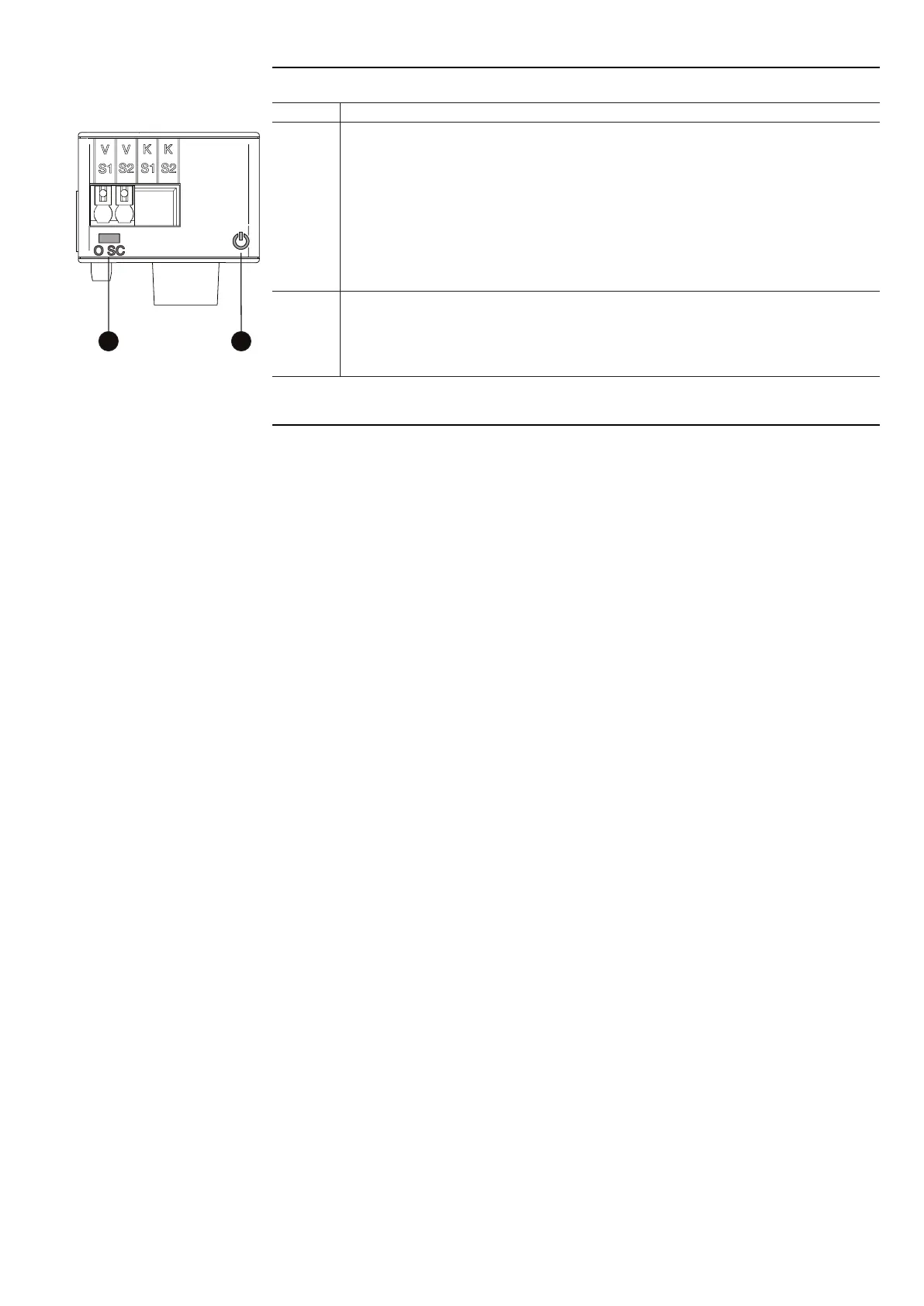
Describes Ekip Signalling 4K as a signalling accessory module with inputs, outputs, and LEDs.
Lists compatible trip units and power supply requirements.
Lists electrical characteristics of output contacts.
Describes Ekip Signalling 2K as a signalling accessory module.
Lists compatible trip units and power supply requirements.
Lists electrical characteristics of output contacts.
Details module mounting and wiring diagrams.
Describes Ekip Com Modbus RTU as a communication module for industrial networks.
Lists compatible trip units and power supply requirements.
Explains the meaning of Power LED and RX/TX LEDs.
Describes Ekip Com Profibus DP as a communication module for industrial networks.
Lists compatible trip units and power supply requirements.
Describes Ekip Com DeviceNet as a communication module for CAN networks.
Lists compatible trip units and power supply requirements.
Details module mounting and wiring diagrams.
Describes Ekip Com Modbus TCP as a communication module for Ethernet networks.
Lists compatible trip units and power supply requirements.
Details module mounting and wiring diagrams.
Explains how to access additional menus for setting function and addressing.
Describes Ekip Com EtherNet/IP™ as a communication module for Ethernet networks.
Lists compatible trip units and power supply requirements.
Details module mounting and wiring diagrams.
Explains how to access additional menus for setting addressing.
Describes Ekip Com IEC 61850 as a communication module for Ethernet networks.
Lists compatible trip units and power supply requirements.
Details module mounting and wiring diagrams.
Explains how to access additional menus for setting modules.
Describes Ekip Link as a communication module for internal Ethernet networks.
Lists functions requiring Ekip Link: Power Controller, Zone Selectivity, Programmable Logic.
Describes how each trip unit functions with Power Controller.
Details how to implement Zone Selectivity using Ekip Link.
Describes Ekip Com Actuator module for opening and closing circuit-breakers remotely.
Details module installation and wiring diagrams.
Details electrical control accessories like YO-YC-YO2-YC2 coils for opening and closing.
Explains the Undervoltage coil YU and its purposes.
Describes AUX 4Q contacts for signalling open/closed state of circuit-breaker.
Describes AUX 6Q contacts for signalling open/closed state of circuit-breaker.
Describes AUX 15Q contacts for signalling open/closed state of circuit-breaker.
Describes AUP contacts for signalling the position of a moving part.
Explains the RTC contact indicating circuit-breaker readiness for closing command.
Explains the S51 contact signalling trip unit tripping.
Describes the S33 M/2 contact signalling the state of closing springs.
Describes KLC locks for securing the circuit-breaker in the open position.
Explains PLC padlocks for securing the circuit-breaker in open position.
Describes the anti-insertion lock for ensuring correct moving part insertion.
Displays the mechanical operation counter.
Explains PLP padlocks for securing the moving part in different positions.
Describes KLP key locks for securing the moving part in different positions.
Describes the SL shutter lock for locking shutters of the fixed part.
Describes DLC lock to prevent switchgear door opening with circuit-breaker closed.
Explains DLP lock to prevent switchgear door opening when moving part is connected/test.
Describes the fail safe device to prevent mobile part removal with charged springs.
Explains Type A interlock for two circuit-breakers to prevent simultaneous closing.
Details Type B interlock for three circuit-breakers with normal and emergency power supplies.
Describes Type C interlock for three circuit-breakers with normal supplies and a bus tie.
Explains Type D interlock for three circuit-breakers on the same bar, allowing only one to be closed.
Provides a sequence of steps for manual closing and opening of the circuit-breaker.
Describes possible states of the circuit-breaker: open/closed with springs discharged/charged.
Details the procedure for inserting the moving part into the fixed part.
Details the procedure for inserting the moving part into the fixed part.
Describes the possible positions of the mobile part of a withdrawable circuit-breaker.
Provides a sequence of steps for manual closing and opening of the circuit-breaker.
Describes possible states of the circuit-breaker: open/closed with springs discharged/charged.
Details the procedure for inserting the moving part into the fixed part.
Guidelines for installing the circuit-breaker in a dry environment.
Lists tests performed for difficult industrial environments.
Recommendations for installing in dusty environments.
States circuit-breaker insensitivity to vibrations.
Explains altitude corrections for dielectric strength and cooling capacity.
Discusses electromagnetic compatibility considerations.
Provides guidelines for storage ambient temperature.
Provides information on overall dimensions and downloadable drawings.
Shows distance for positioning anchor plates for E1.2 according to peak current.
Shows distance for positioning anchor plates for E2.2-E6.2 according to peak current.
Details the earth connection screw and procedure.
Describes phase separators for insulation clearance.
Explains connection to the power circuit using busbars and tightening torques.
Lists protection degrees like IP20, IP30, and optional IP54.
Provides tables for dissipated power of Emax 2 circuit-breakers according to IEC 60947.
Provides tables showing derating percentages for different temperatures.
Describes current-limiting features of Emax 2 series circuit-breakers.
Lists standard accessories for fixed Emax 2 circuit-breakers.
Lists standard accessories for withdrawable Emax 2 circuit-breakers.
Explains how the protection trip unit identifies and signals faults.
Lists possible fault situations, their causes, and suggestions for resolution.
Lists faults detected from the display and suggestions for resolution.
Introduces LEAP objectives, characteristics, and report content.
States the aims of the LEAP program: extending life and preventing faults.
Describes LEAP EASY AUDIT as a customer-performed analysis.
Explains LEAP AUDIT as an analysis performed by ABB personnel.
Describes LEAP STAND ALONE as an analysis by an ABB specialist technician.
Introduces LEAP + PMP as a complete analysis and preventive maintenance program.
Introduces PowerCare, a range of service packages for electrification systems.
Discusses the variety of devices in electrical installations and the need for management.
Explains the PowerCare platform and its service offerings.
Describes the PowerCare matrix structure.
Defines service areas offered by ABB technical support.
Explains that levels represent the extent of service offered.