ABB | SACE Emax 2
Electronic accessories | 11 - Ekip Com Profinet modules227 | © 2017 ABB | 1SDH001330R0002 - ECN000058721 Rev. A
Connections
The modules must be mounted on the terminal box of the circuit-breaker or of the fixed part of the withdrawable
circuit-breaker, in the first free slot after the Ekip Supply module.
Information on the assembly is available on the website http://www.abb.com/abblibrary/DownloadCenter/, in
particular in the kit sheet 1SDH001000r0514.
An example with an E2.2 circuit-breaker in fixed and withdrawable versions is provided to the side.
The following is a view of the terminal box of E1.2 and E2.2-E4.2-E6.2 circuit-breakers with the relevant wiring
diagram:
R2
R1
U2
U1
38
36
35
98
96
95
YRMS33S51
YO
EKIP SupplyTrip Unit I/O
Ge-
Ge
Szc
K2
K1
W4
W3
Q4Q3Q2Q1YC
YU
YO2
RTC
I/O
TU
44
42
41
34
32
31
24
22
21
14
12
11
C12
C13
C11
C2
C3
C1
D2
D1
48
46
45
Ne
Rca
Ne-
Gzi
Szo
Szi
Gzo
Rct
Vn
V1
V2
V3
Module Module
YO
01
H4
02
K5
04
K10K9
94
92
H3
9181
H2
82
K4
K8
8474
K7
K3
H1
72
7161
HC
62
64
54
52
51
EKIP SupplyModuleTrip Unit I/O
HC
K6
Ge-
Ge
Szc
K2
K1
W4
W3
R2
R1
Q4Q3Q2Q1YC2YC
YU
YO2
RTC
I/O
TU
44
42
41
34
32
31
24
22
21
14
12
11
C22
C21
C12
C13
C11
C2
C3
C1
D2
D1
48
46
45
Ne
Rca
Ne-
Gzi
Szo
Szi
Gzo
Rct
Vn
V1
V2
V3
U2
U1
38
36
35
98
96
95
YRMS33S51
EKIP Signalling 4KQ5..Q10
Module Module
HC
A4
A3
A4
54
194
XK7 XK7
1
2
193
S75I/5
W10
RJ45
BUS 1
Ekip
Com Profinet
n
COM
K51
O)
*
*L)
n
Ekip
Com Redundant
Profinet
BUS 2
RJ45
W10R
64
COM
K51
*L)
R)
*
R)
*
Diagrams 54 - 64
For the communication bus, a cable of type Cat.6 S/FTP must be used (Cat.6 with S/FTP double shielding).
If the circuit-breaker is in withdrawable version, the use of cables fitted with a RJ45 socket with output at 90°
is recommended.
Further information is available on page 174, or on the website http://www.abb.com/abblibrary/
DownloadCenter/, where the wiring diagram is available 1SDm000091r0001.
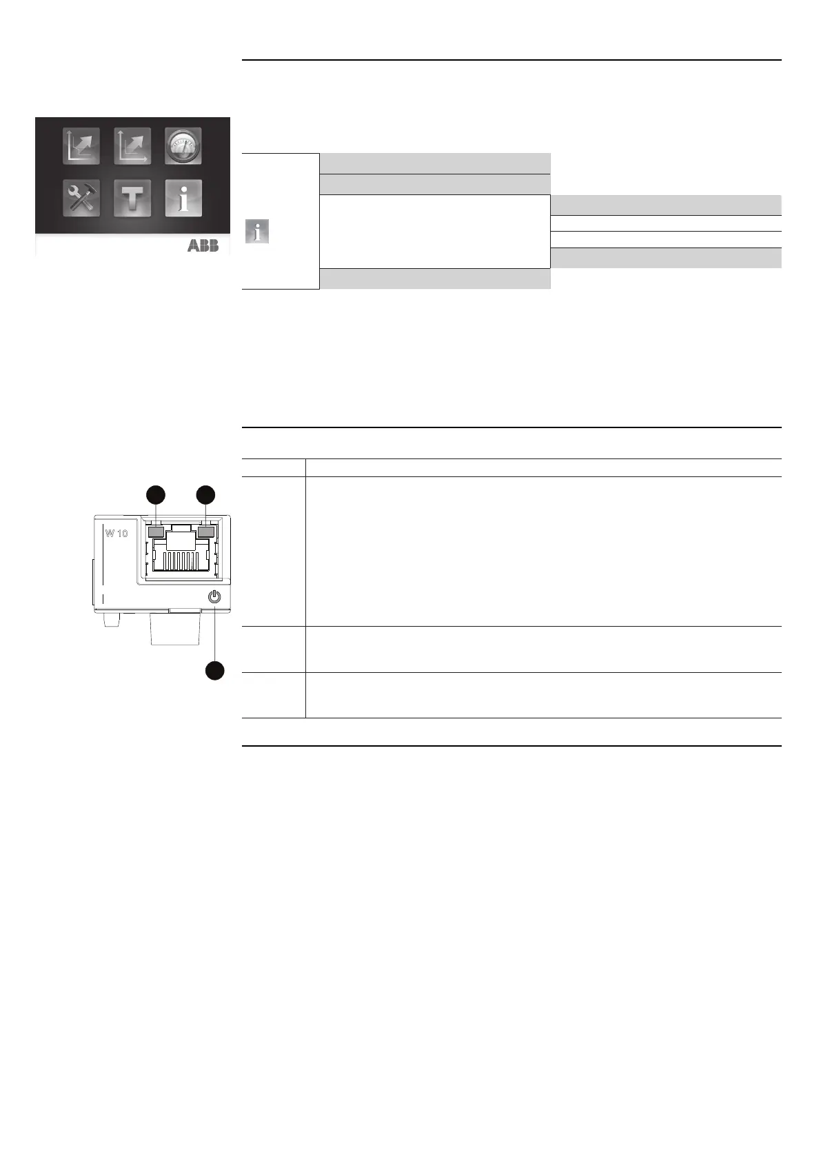
Access from the display
With the modules energized and Local Bus enabled, the modules can be viewed on the display.
To enable the Local Bus, you need to select "On" in the menu Settings - Modules - Local Bus.
The following table shows the path from the display for accessing information on the modules:
About
Protection Unit
Circuit-breaker
Modules
…
Ekip Com Profinet
Ekip Com Profinet *R
…
Power Controller
Information that can be displayed on the modules:
• The serial number and the software version.
• The MAC address, assigned by ABB and with an OUI equal to ac:d3:64 (Organizationally Unique Identifier,
formed of the first three bytes of a MAC address; the OUI uniquely identifies the manufacturer of an
Ethernet device).
Signallings
A
B
C
The following table shows the possible signals, and their meaning:
Pos. Description
A
Power LED, green. The possible states are:
• Off: power supply absent.
• On fixed: power supply and communication with the trip unit present (with a trip unit with
the Alive LED option disabled).
• On, with one flash per second (synchronized with that of the green LED on the trip unit):
power supply and communication with trip unit present (with a trip unit with the Alive LED
option enabled).
• On, with two quick flashes per second (not synchronized with those of the green LED on
the trip unit): power supply present, and communication with trip unit absent (for example:
because of Local Bus disabled).
B
Link LED, green. The possible states are:
• Off: connection error (signal absent).
• On fixed: correct connection.
C
Activity LED, yellow. The possible states are:
• Off: no activity on the line.
• On flashing: activity on the line (in reception and/or transmission).

 Loading...