223
Chapter 4 Remote Interface Reference
Phase-Lock Commands
4
Phase-Lock Commands
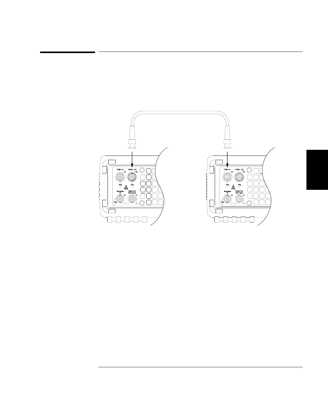
The rear-panel 10 MHz In and 10 MHz Out connectors allow
synchronization between multiple Agilent 33250As (see connection
diagram below) or to an external 10 MHz clock signal. You can also
control the phase offset from the front panel or over the remote interface.
PHASe {<angle>|MINimum|MAXimum}
PHASe? [MINimum|MAXimum]
Adjust the phase offset of the output waveform in degrees or radians as
specified by the previous UNIT:ANGL command (not available for pulse
and noise). Select from -360 degrees to +360 degrees or -2
π
to +2
π
radians
.
The default is 0 degrees (0 radians). MIN = -360 degrees (-2π radians).
MAX = +360 degrees (+2π radians). The PHAS? query returns the phase
offset in degrees or radians.
• The specified phase adjustment causes a “bump” or “hop” in the
output waveform in order to change the phase relationship to the
external signal to which it is currently locked.
• This phase adjustment for phase-lock applications is independent of
the burst phase as set by the BURS:PHAS command (see page 191).

 Loading...


