6
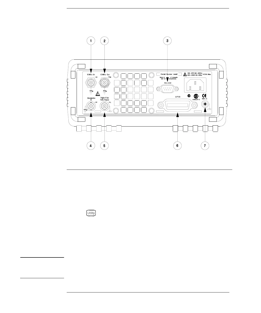
The Rear Panel at a Glance
WARNING For protection from electrical shock, the power cord ground must not be
defeated. If only a two-contact electrical outlet is available, connect the
instrument’s chassis ground screw (see above) to a good earth ground.
1
External 10 MHz Reference Input Terminal
2
Internal 10 MHz Reference Output Terminal
3 RS-232 Interface Connector
4 External Modulation Input Terminal
5
Input: External Trig/FSK/Burst Gate
Output: Trigger Output
6 GPIB Interface Connector
7 Chassis Ground
Use the menu to:
• Select the GPIB or RS-232 interface (see chapter 2).
• Select the GPIB address (see chapter 2).
• Set the RS-232 baud rate, parity, and handshake mode (see chapter 2).

 Loading...


