297
Chapter 7 Tutorial
Direct Digital Synthesis
4
7
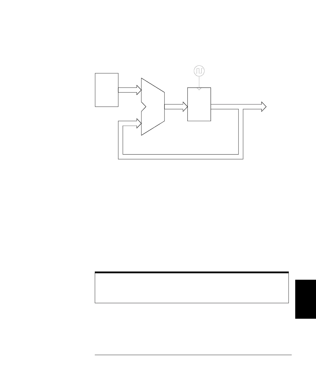
Phase Accumulator Circuitry
The 33250A uses a 64-bit phase accumulator which yields 2
-64
x
200 MHz
or 10.8 picohertz frequency resolution internally. Note that only the
14 or 16 most-significant bits of the Phase Register are used to address
waveform memory. Therefore, when synthesizing low frequencies
(less than 12.21 kHz), the address will not change during every clock
cycle. However, at higher frequencies (greater than 12.2 kHz),
the address will change by more than one location during each clock
cycle and some points will be skipped. If too many points are skipped,
a phenomenon known as “aliasing” will occur and the waveform output
will become somewhat distorted.
200 MHz
Waveform
Phase
Adder
64 Bits
Phase
Register
Register (PIR)
64 Bits
MSBs
(
14 or 16 bits
)
Memory
Address
Increment
64 Bits
The Nyquist Sampling Theorem states that in order to prevent aliasing,
the highest frequency component of the desired output waveform must
be
less than half of the sampling frequency (100 MHz for the 33250A).

 Loading...


