306
Chapter 7 Tutorial
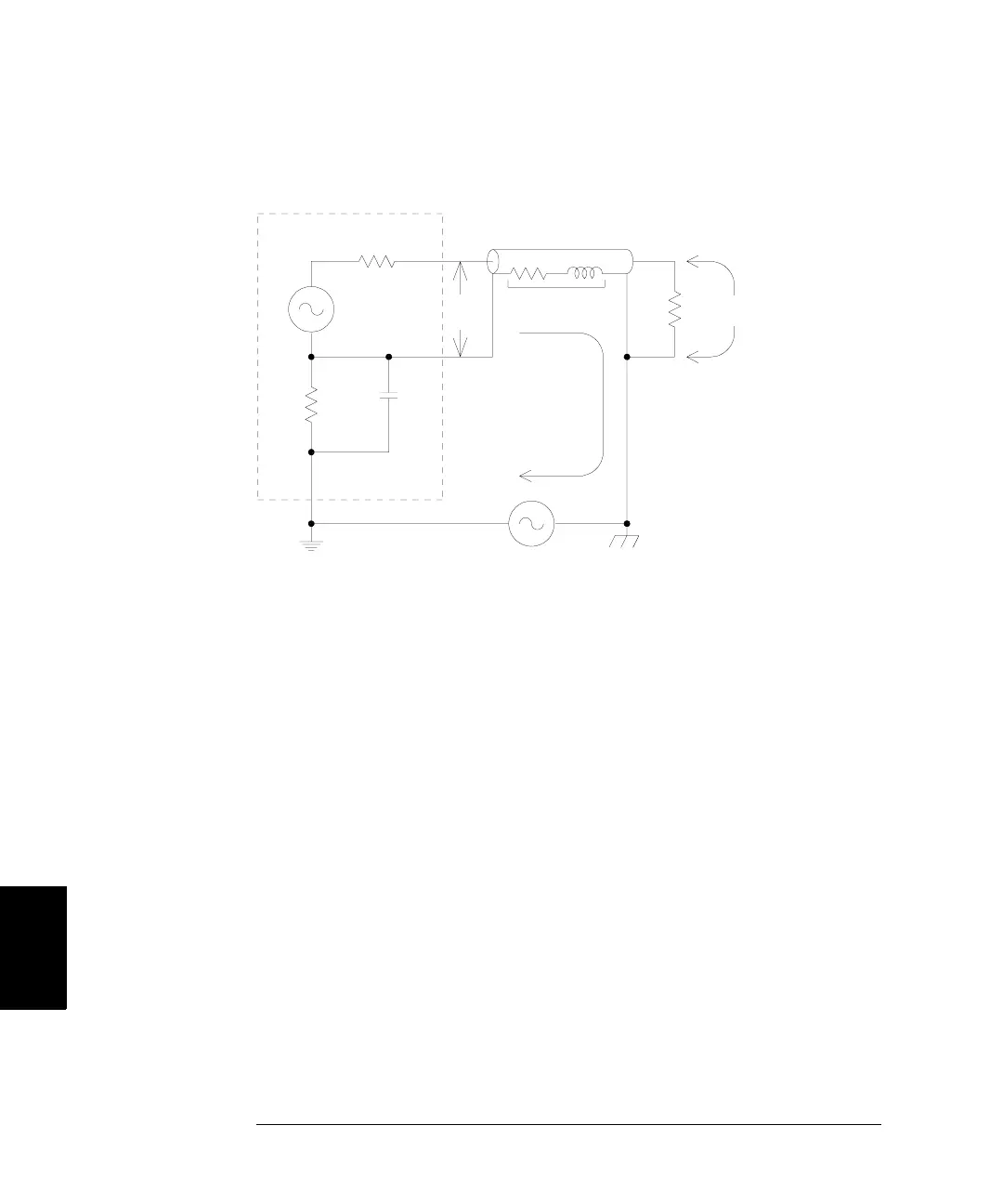
Ground Loops
7
Ground Loop Effects
At frequencies above a few kilohertz, a coaxial cable’s shield becomes
inductive, rather than resistive, and the cable acts as a transformer.
When this happens, it tends to force the shield and center-conductor
currents to be equal but opposite. For any voltage drop in the shield due
to I
GND
, there is a similar drop in the center conductor. This is known as
the balun effect and it reduces ground loops at higher frequencies.
Note that lower shield resistance causes the balun effect to become more
of a factor at lower frequencies. Therefore, coaxial cables with two or
three braided shields are much better than those with single braids.
To reduce errors due to ground loops, connect the function generator to
the load using a high-quality coaxial cable and ground it at the load
through the cable’s shield. If possible, make sure the function generator
and the load are connected to the same electrical outlet to minimize
further differences in ground potential.
Agilent 33250A
50Ω
V
GEN
R
L
V
L
= V
OUT
– (I
GND
x Z
Shield
)
V
OUT
Z
Shield
1 MΩ
45 nF
I
GND
V
GND

 Loading...


