311
Chapter 7 Tutorial
Modulation
4
7
Frequency Modulation (FM) For FM, the DSP uses modulation
samples to modify the output frequency of the instrument by changing
the content of the PIR (see “Direct Digital Synthesis” on page 295).
Note that since the rear-panel Modulation In connector is dc-coupled,
you can use the 33250A to emulate a voltage-controlled oscillator (VCO).
The variation in frequency of the modulating waveform from the carrier
frequency is called the frequency deviation. Waveforms with frequency
deviations less than 1% of the modulating signal’s bandwidth are
referred to as narrowband FM. Waveforms with larger deviations are
referred to as wideband FM. The bandwidth of the modulated signal can
be approximated by the following equations.
BW
≅
2
x
(Modulating Signal Bandwidth)
For narrowband FM
BW
≅
2
x
(Deviation + Modulating Signal Bandwidth)
For wideband FM
In the United States, commercial FM stations usually have a modulation
bandwidth of 15 kHz and deviation of 75 kHz, making them “wideband”.
Therefore,
the modulated bandwidth is: 2
x
(75 kHz + 15 kHz) = 180 kHz
.
Channel spacing is 200 kHz.
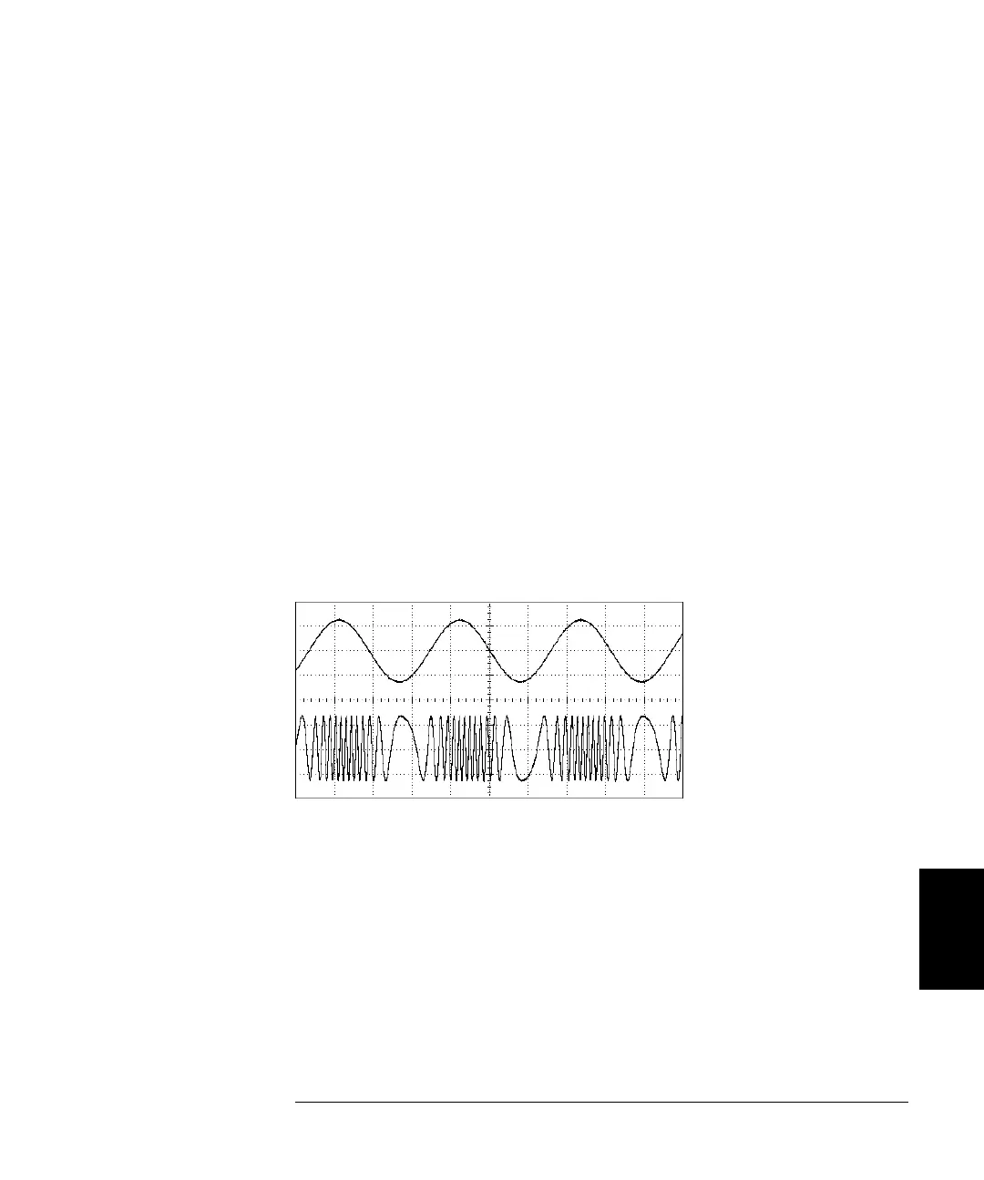
Frequency Modulation
Modulating Signal
Modulated Carrier

 Loading...


