
Do you have a question about the Agilent Technologies 8922M and is the answer not in the manual?
| Frequency Resolution | 1 Hz |
|---|---|
| Harmonic Distortion | -30 dBc |
| Non-Harmonic Spurious | -60 dBc |
| RF Generator Frequency Resolution | 1 Hz |
| RF Generator Output Power Resolution | 0.1 dB |
| RF Receiver Frequency Resolution | 1 Hz |
| Audio Generator Frequency Range | 20 Hz to 20 kHz |
| Audio Analyzer Frequency Range | 20 Hz to 20 kHz |
| Modulation Types | AM, FM |
| Amplitude Accuracy | ±1.0 dB |
| Dimensions | 177 mm |
| Power | 100-240 VAC, 50/60 Hz |
| Weight | 20.4 kg (45 lbs) |
Details on selecting and installing fuses and power cords for the instrument.
Provides a step-by-step guide for the initial setup and connection of the instrument.
Covers operational environment, instrument options, and general specifications.
Explains the three main operating modes: Active Cell, Test Mode, and CW Generator.
Details the default mode for base station emulation and call setup.
Describes how to test the mobile phone without setting up a call.
Explains configuring the instrument as a Continuous Wave signal generator.
Overview of available GSM and ancillary measurements.
Troubleshooting common measurement issues and error messages.
Details advanced screens and capabilities for experienced users.
Information on preparing for performance verification tests.
Lists the required test equipment for performance verification.
Instructions for installing and running the performance test software.
Explains the theory and equipment for each performance test.
Guideline to identify hardware assemblies causing test failures.
Detailed technical specifications for the Agilent 8922M/S.
Explains different types of input fields: Alphanumeric, Data Entry, Choices.
Details settings for measuring audio frequency and voltage.
Provides settings for Bit Error Rate measurements.
Offers advanced Bit Error Rate measurement display options.
Configures GSM 900 cell parameters for base station emulation.
Configures E-GSM, DCS 1800, PCS 1900 cell parameters.
Manages call setup and provides access to measurement screens.
Active Cell mode with additional diagnostic information.
Enables testing of mobile phones without a call setup.
Configures the instrument as a CW Signal Generator.
Provides control for additional cell parameters and states.
Instrument setup, radio type, and I/O configuration.
Displays carrier frequency and power of continuous signals.
Provides a faster Bit Error Rate measurement.
Configures printer, GPIB, and serial port settings.
Controls protocol logging via the Protocol Interface port.
Defines settings for synchronization during measurements.
Records and displays instrument messages.
Displays mobile station information and signaling status.
Main controls for viewing and measuring oscilloscope traces.
Controls for setting up oscilloscope trigger signals.
Controls for manipulating oscilloscope markers.
Displays RF spectrum power spectral density vs frequency.
Displays RF spectrum power spectral density vs time.
Measures phase and frequency error with multi-burst disabled.
Measures phase and frequency error with multi-burst enabled.
Displays phase error versus time, scaled to measurement.
Displays measured demodulated data bits and interpretation tags.
Displays the rising portion of the amplitude envelope with mask.
Displays the middle portion of the amplitude envelope with mask.
Displays the falling portion of the amplitude envelope with mask.
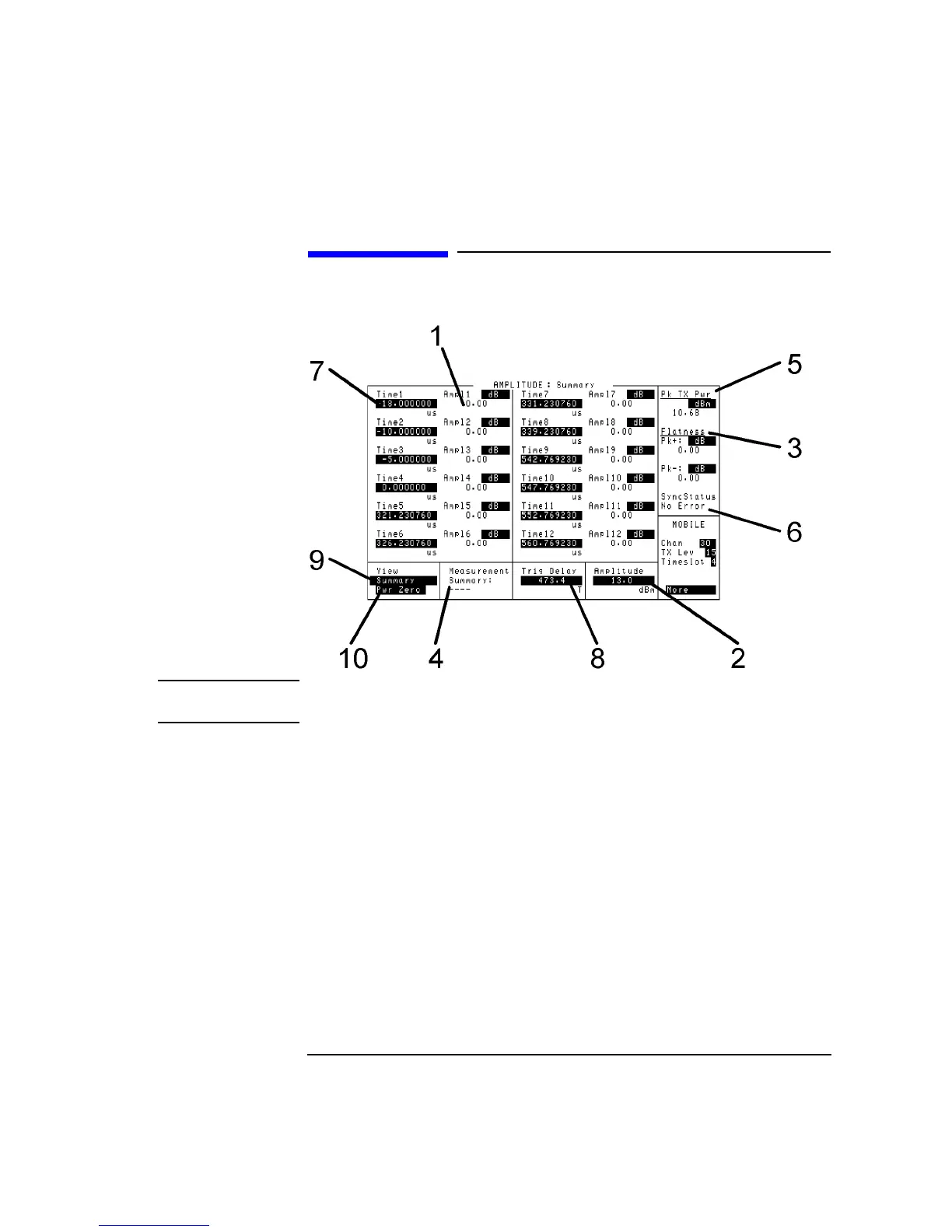
Provides a summary of amplitude measurements at selected time fields.
Displays Pulse On/Off power spectral density vs time for rising portion.
Displays Pulse On/Off power spectral density vs time for rising portion.
Displays Pulse On/Off power spectral density vs time for falling portion.
Controls AF generator audio output amplitude, coupling, and frequency.
Sets RF analyzer accuracy, AGC mode, amplitude, and control.
Controls RF generator amplitude, DC AM, frequency, and GMSK.
Access to service documentation and screen.
Tests mobile station's ability to receive and display broadcast messages.
Displays spectrum analyzer power spectral density vs frequency trace.
Controls RF generator settings within the spectrum analyzer.
Controls marker position and reference level for spectrum analysis.
Adjusts input attenuator, video bandwidth, and RF input port.
Access to the IBASIC Test Software Applications.
Diagram illustrating the layout and labeling of the instrument's keys.
Details on keys for operations like ADRS, ASSIGN, AVG, CANCEL, CELL CNTL.
Explains the use and assignment of local keys L1 and L2.
Explains the use and assignment of global keys G1, G2, and G3.
Describes how to change measurement units using applicable keys.
Detailed description of each front-panel connector and its function.
Detailed description of each rear-panel connector and its function.
Provides pin assignments and signal descriptions for the SYSTEM BUS connector.
Illustrates timing specifications for various signals and operations.
Lists communication failure messages requiring instrument power cycle.
Describes firmware revision errors and contact information.
Displays synchronization errors and multi-burst measurement progress.
Details protocol errors generated by various sublayers and their causes.
Provides a brief description and values for various timers.
Lists error codes for physical, data link, RR, MM, and CC layers.
Provides examples of Common Air Interface protocol logs for typical calls.
Guidance on monitoring and recovering from protocol errors.
Introduction to the HP Instrument BASIC computer and its capabilities.
Covers controlling the instrument and connected GPIB devices.
Instructions for managing IBASIC programs and test procedures.
Methods for entering and editing IBASIC programs.
Information on memory cards and programming the instrument.
Concepts and tasks for developing programs with the TESTS subsystem.
Explains the purpose of Protocol Logging and its availability.
Lists the necessary equipment for Protocol Logging setup.
Illustrates cabling setup for connecting the Agilent 8922M and HP/Agilent 37900D.
Instructions for setting up the Agilent 8922M, including camp on and logging.
Configuration steps for the HP/Agilent 37900D for communication.
Procedure for capturing protocol messages for analysis.
Details on logging screen controls and remote protocol logging.
Provides a detailed log of a typical call's Common Air Interface messages.
Absolute Radio Frequency Channel Number.
Broadcast Channel, used for service acquisition and network identification.
Broadcast Control Channel, transmits network identification and cell info.
Measures recovered information quality, equivalent to SINAD.
Base Station.
Base Transceiver System.
Measures equivalent Class II BER using a new loopback path.
Process to arrange error-protected speech data for RF transmission.
Most important data bits in error correction, subdivided into Ia and Ib.
Slowly changing data bits receiving no error correction.
Cyclic Redundancy Check for detecting errors.
Digital Cellular System at 1.8 GHz, designed for higher user densities.
Process to correct for fading in digital radios.
Methods to provide voice quality under fading conditions.
Fast Associated Control Channel, used for handover information.
A repetitive collection of time slots in a TDMA system.
Gaussian Filtered Minimum Shift Keying, used in GSM systems.
Global System for Mobile Communication, 900 MHz band.
Measures phase trajectory difference for GSM transmitters.
Buffer bits between adjacent data packets.
International Mobile Subscriber Identification number.
Minimum Shift Keying modulation technique.
Personal Communications System used in the USA around 1.9 GHz.
Pseudo-Random Bit Sequence for bit error testing.
Tests mobile phone's ability to turn its transmitter on and off.
Random Access Channel, used for mobile timing advance notification.
Regular Pulse Excitation Long Term Prediction for voice conversion.
Received Signal Strength Indicator.
Slow Associated Control Channel for slow control information.
Stand-alone Dedicated Control Channel for call setup and holding.
Subscriber ID Module card storing subscriber information.
Short Message Service Cell Broadcast for unacknowledged messages.
Converts audio signal to data, minimizing bits.
Delay between trigger event and measurement start.


