Home
Agilent Technologies
Multimeter
U1252B
Agilent Technologies U1252B User Manual
4
of 1
of 1 rating
191 pages
Give review
Manual
Specs
To Next Page
To Next Page
To Previous Page
To Previous Page
Loading...
80
Agilent U1251B/U1
252B User’s and Service Guide
4
Changing The Default Setting
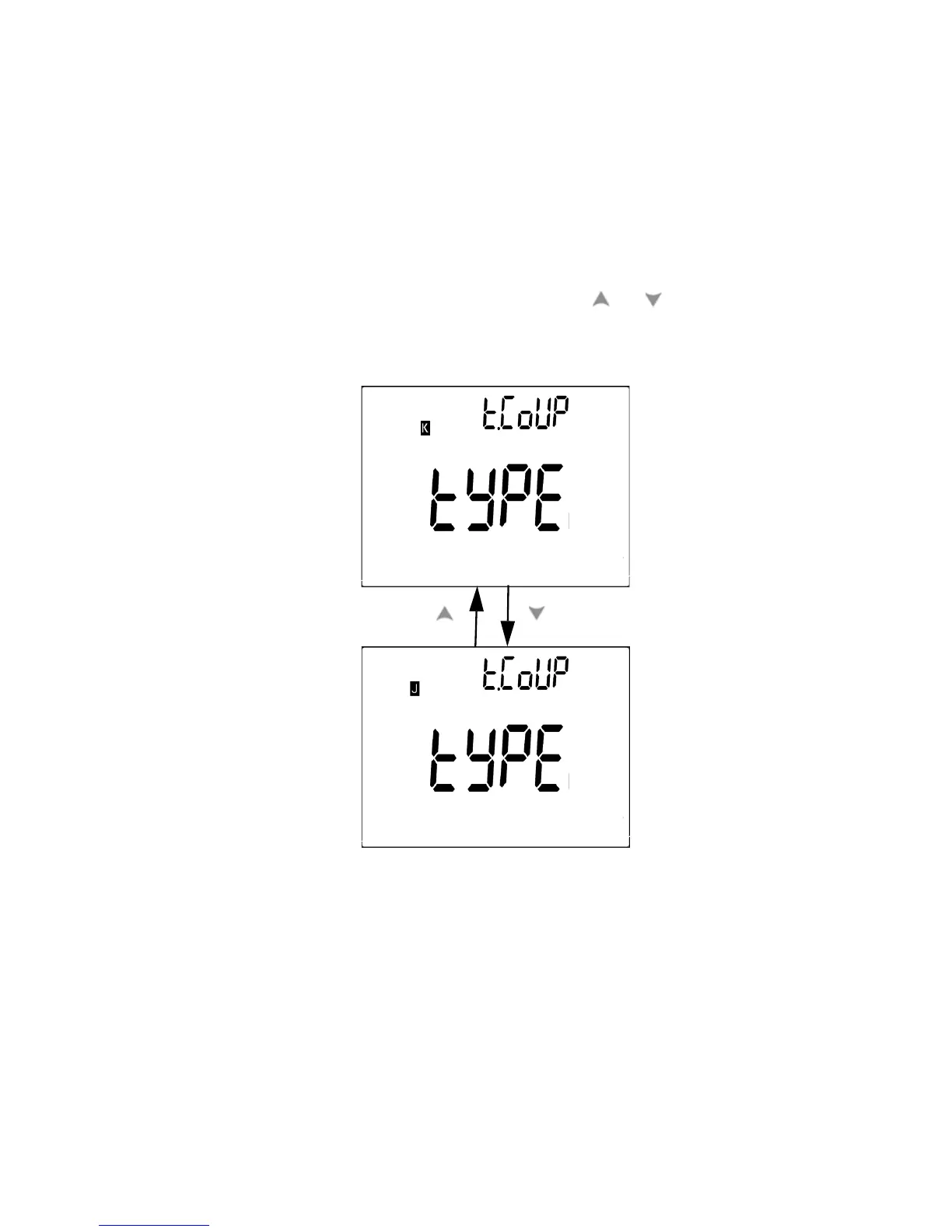
Setting Thermocouple T
ypes (U1252B only)
The ther
mocouple sensor types t
hat can be selected are type
K
(
d
e
f
a
u
l
t
)
o
r
t
y
p
e
J
.
P
r
e
s
s
o
r
t
o
s
w
i
t
c
h
b
e
t
w
e
e
n
t
h
e
J and the K type.
Figure 4-3
Ther
mocouple type setup
Press
99
101
Table of Contents
Default Chapter
3
Safety Symbols
3
General Safety Information
4
Safety Information
4
In this Guide
8
Table of Contents
11
1 Getting Started
22
Introducing the U1251B/U1252B Handheld Digital Multimeter
22
Check the Shipment
23
Adjusting the Tilt-Stand
24
Figure 1-1 Tilt-Stand at 60
24
Figure 1-2 Tilt-Stand at 30
24
Figure 1-3 Tilt-Stand at Hanging Position
25
The Front Panel at a Glance
26
Figure 1-4 U1252B Front Panel
26
The Rear Panel at a Glance
27
Figure 1-5 Rear Panel
27
The Rotary Switch at a Glance
28
Figure 1-6 Rotary Switch
28
Table 1-1 Rotary Switch Description and Functions
28
The Keypad at a Glance
29
Figure 1-7 U1252B Keypad
29
Table 1-2 Keypad Descriptions and Functions
29
The Display at a Glance
31
Figure 1-8 Display Symbols
31
Table 1-3 General Display Symbols
32
Table 1-4 Primary Display Symbols
33
Table 1-5 Secondary Display Symbols
34
Selecting Display with the Hz Button
35
Table 1-6 Analog Bar Range and Counts
35
Table 1-7 Selecting Display with the Hz Button
36
Selecting Display with the Dual Button
37
Table 1-8 Selecting Display with the Dual Button
38
Selecting Display with the Shift Button
40
Table 1-9 Selecting Display with the Shift Button
40
The Terminals at a Glance
42
Figure 1-9 Connector Terminals
42
Table 1-10 Terminal Connections for Different Measuring
42
2 Making Measurements
43
Figure 2-17 Charge Terminal Alert
43
Measuring Voltage
44
Table 2-1 Numerical Steps Descriptions
44
Figure 2-1 Measuring AC Voltage
45
Measuring AC Voltage
45
Figure 2-2 Measuring DC Voltage
46
Measuring DC Voltage
46
Understanding the Measurement Instructions
44
Measuring Current
47
Μa & Ma Measurement
47
Figure 2-3 Measuring Ma and Ma Current
48
Percentage Scale of 4 Ma to 20 Ma
49
Table 2-2 Percentage Scale and Measurement Range
49
Figure 2-4 Measuring Scale of 4-20 Ma
50
A (Ampere) Measurement
51
Figure 2-5 a (Ampere) Current Measurement
51
Frequency Counter
52
Figure 2-6 Measuring Frequency
53
Figure 2-7 Measuring Resistance
54
Measuring Resistance, Conductance and Testing Continuity
54
Figure 2-8 Audible Continuity, Conductance, and Resistance
55
Table 2-3 Audible Continuity Measurement Range
56
Figure 2-9 Conductance Measurement
57
Testing Diodes
58
Figure 2-10 Measuring Forward Bias of Diode
59
Figure 2-11 Measuring Reverse Bias of Diode
60
Measuring Capacitance
61
Figure 2-12 Capacitance Measurements
62
Measuring Temperature
63
Figure 2-13 Connecting the Thermal Probe into the Non-Compensation Transfer Adapater
64
Figure 2-14 Connecting the Probe with Adapter into the
64
Figure 2-15 Surface Temperature Measurement
66
Alerts and Warning During Measurement
67
Overload Alert
67
Input Warning
67
Figure 2-16 Input Terminal Warning
67
Charge Terminal Alert
68
3 Functions and Features
69
Dynamic Recording
70
Figure 3-1 Dynamic Recording Mode Operation
71
Data Hold (Trigger Hold)
72
Figure 3-2 Data Hold Mode Operation
72
Refresh Hold
73
Figure 3-3 Refresh Hold Mode Operation
74
Null (Relative)
75
Figure 3-4 Null (Relative) Mode Operation
76
Decibel Display
77
Figure 3-5 Dbm/Dbv Display Mode Operation
78
Ms Peak Hold
79
Figure 3-6 1 Ms Peak Hold Mode Operation
80
Data Logging
81
Manual Logging
81
Figure 3-7 Hand (Manual) Logging Mode Operation
82
Figure 3-8 Full Log
82
Interval Logging
83
Figure 3-9 Interval (Automatic) Logging Mode Operation
84
Reviewing Logged Data
85
Figure 3-10 Log Review Mode Operation
86
Square Wave Output (for U1252B)
87
Figure 3-11 Frequency Adjustment for Square Wave Output
88
Figure 3-12 Duty Cycle Adjustment for Square Wave Output
89
Figure 3-13 Pulse Width Adjustment for Square Wave Output
90
Remote Communication
91
Figure 3-14 Cable Connection for Remote Communication
91
4 Changing the Default Setting
94
Selecting Setup Mode
94
Table 4-1 Available Setting Options in Setup Mode
95
Setting Data Hold/Refresh Hold Mode
98
Figure 4-1 Data Hold/Refresh Hold Setup
98
Setting Data Logging Mode
99
Figure 4-2 Data Logging Setup
99
Setting Thermocouple Types (U1252B Only)
100
Figure 4-3 Thermocouple Type Setup
100
Setting Reference Impedance for Dbm Measurement
101
Figure 4-4 Reference Impedance for Dbm Measurement Setup
101
Setting Minimum Frequency Measurement
102
Figure 4-5 Minimum Frequency Setup
102
Setting Temperature Unit
103
Figure 4-6 Temperature Unit Setup
104
Setting Auto Power Saving Mode
105
Figure 4-7 Auto Power Saving Setup
106
Setting Percentage (%) Scale Readout
107
Figure 4-8 % Scale Readout Setup
107
Figure 4-9 Beep Frequency Setup
108
Setting Beep Frequency
108
Figure 4-10 Backlit Timer Setup
109
Setting Backlight Timer
109
Setting Baud Rate
110
Figure 4-11 Baud Rate Setup Remote Control
110
Setting Parity Check
111
Figure 4-12 Parity Check Setup
111
Setting Data Bit
112
Figure 4-13 Data Bit Setup for Remote Control
112
Setting Echo Mode
113
Figure 4-14 Echo Mode Setup for Remote Control
113
Setting Print Mode
114
Figure 4-15 Print Mode Setup for Remote Control
114
Returning to Default Factory Settings
115
Figure 4-16 Reset Setup
115
Setting the Battery Voltage
116
Figure 4-17 Battery Voltage Selection
116
Setting the DC Filter
117
Figure 4-18 DC Filter
117
5 Maintenance
119
Introduction
120
General Maintenance
120
Battery Replacement
120
Storage Considerations
122
Figure 5-1 9 V Rectangular Battery
122
Charging the Battery
123
Table 5-1 Battery Voltage and Corresponding Percentage of Charg
124
Figure 5-2 Battery Capacity Display as Trickle
125
Figure 5-3 Self-Test
126
Table 5-2 Error Messages
126
Figure 5-4 Charging Mode
128
Figure 5-5 Charge End and Trickle State
128
Figure 5-6 Battery Charging Procedure
129
Fuse Checking Procedure
130
Figure 5-7 Fuse Checking Procedures
130
Table 5-3 Measurement Readings for Fuse Checking
131
Replacing the Fuse
132
Figure 5-8 Fuse Replacement
133
Table 5-4 Fuse Specifications
133
Troubleshooting
134
Table 5-5 Basic Troubleshooting Procedures
134
Replaceable Parts
135
To Order Replaceable Parts
135
6 Performance Tests and Calibration
138
Calibration Overview
138
Closed-Case Electronic Calibration
138
Agilent Technologies Calibration Services
138
Calibration Interval
139
Adjustment Is Recommended
139
Recommended Test Equipment
140
Table 6-1 Recommended Test Equipment
140
Basic Operating Test
141
Backlit Test
141
Testing the Display
141
Figure 6-1 LCD Display
141
Current Terminal Test
142
Figure 6-2 Input Warning
142
Charge Terminal Alert Test
143
Figure 6-3 Charge Terminal Alert
143
Test Considerations
144
Calibration Security
145
Performance Verification Tests
146
Table 6-2 Verification Test
147
Performance Tests and Calibration
152
Unsecuring the Instrument for Calibration
154
Calibration Process
157
Using the Front Panel for Adjustments
158
Adjustments Consideration
159
Valid Adjustment Input Values
160
Table 6-3 Valid Adjustment Input Values
160
Adjustment Procedure
161
Table 6-4 Adjustment Table
163
Finishing the Adjustment
168
To Read the Calibration Count
168
Calibration Errors
169
Table 6-5 Calibration Error Codes and Their Respective
169
7 Specifications
171
Product Characteristics
172
Measurement Category
175
Measurement Category Definition
175
Specification Assumptions
176
Electrical Specifications
176
DC Specifications
176
Table 7-1 DC Accuracy ± (% of Reading + Number of Least Signifi- Cant Digit)
177
AC Specifications
179
Table 7-2 U1251B Accuracy Specifications
179
AC+DC Specifications for U1252B
181
Table 7-6 U1252B True RMS Ac+DC Voltage Specifications
181
Table 7-7 U1252B True RMS Ac+DC Current Specifications
181
Capacitance Specifications
182
Temperature Specifications
182
Table 7-8 Capacitance Specifications
182
Table 7-9 Temperature Specifications
182
Frequency Specifications
183
Duty Cycle and Pulse Width Specifications
183
Table 7-10 Frequency Specifications
183
Table 7-11 Duty Cycle and Pulse Width Specifications
183
Frequency Sensitivity Specifications
184
Table 7-12 Frequency Sensitivity and Trigger Level Specifications for
184
Table 7-13 Frequency Sensitivity Specifications for Current
185
Peak Hold Specifications
186
Frequency Counter Specifications for U1252B
186
Table 7-14 Peak Hold Specifications for DC Voltage and Current
186
Table 7-15 Frequency Counter (Divide by 1) Specifications
186
Square Wave Output for U1252B
187
Table 7-16 Frequency Counter
187
Table 7-17 Square Wave Output Specifications
187
Operating Specifications
189
Display Update Rate (Approximate)
189
Table 7-18 Display Update Rate (Approximate)
189
Input Impedance
190
Table 7-19 Input Impedance
190
4
Based on 1 rating
Ask a question
Give review
Questions and Answers:
Need help?
Do you have a question about the Agilent Technologies U1252B and is the answer not in the manual?
Ask a question
Agilent Technologies U1252B Specifications
General
Brand
Agilent Technologies
Model
U1252B
Category
Multimeter
Language
English
Related product manuals
Agilent Technologies U1253B
225 pages
Agilent Technologies U1251A
169 pages
Agilent Technologies U1241B
89 pages
Agilent Technologies U1242B
89 pages
Agilent Technologies U1242A
85 pages
Agilent Technologies U1241A
85 pages
Agilent Technologies U1231A
133 pages
Agilent Technologies U3402A
127 pages
Agilent Technologies U3606A
288 pages
Agilent Technologies 3458A
372 pages
Agilent Technologies 34401A
242 pages
Agilent Technologies 34410A
144 pages

 Loading...


