Maintenance 5
Agilent U1251B/U1252B User’s and Service Guide 111
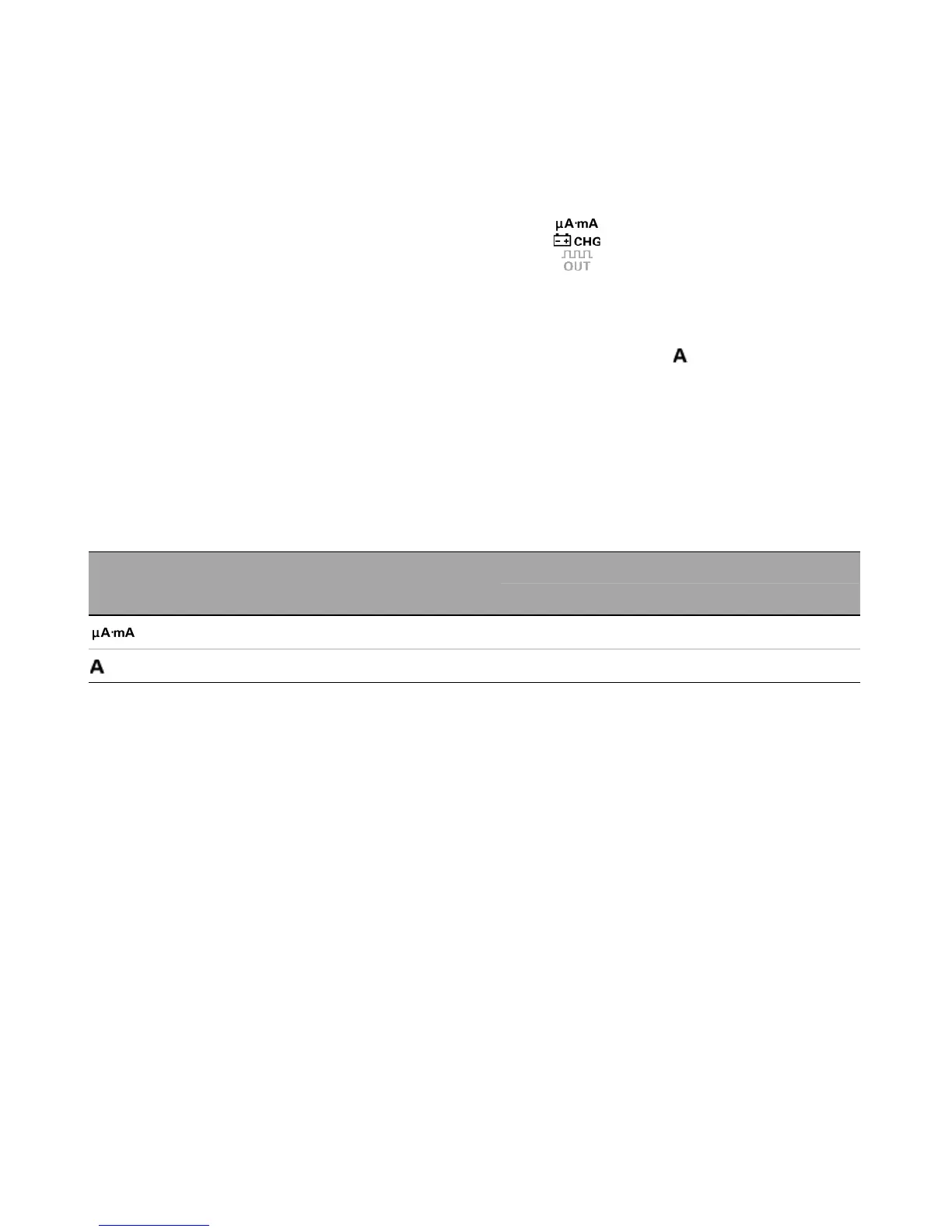
3 To test Fuse 1, place the tip of the test probe on the right
half of input terminal . Ensure that the probe tip
touches the metal inside the input terminal, as shown in the
figure above.
4 To test Fuse 2, place and touch the tip of the test probe
on the right half of input terminal . Ensure that the
probe tip touches the metal inside the input terminal.
5 Observe the reading on the instrument's display. Refer to
Table 5- 3 below for the possible readings that could
appear).
6 Replace the fuse when OL is displayed.
Tab l e 5-3 Measurement readings for fuse checking
Current input terminal Fuse Fuse rating
Fuse OK (approximately) Replace fuse
Displayed readings
1 440 mA/1000 V 6.2 MΩ OL
2 11 A/1000 V 0.06 Ω OL

 Loading...


