Getting Started Tutorial 1
Agilent U1251B/U1252B User’s and Service Guide 15
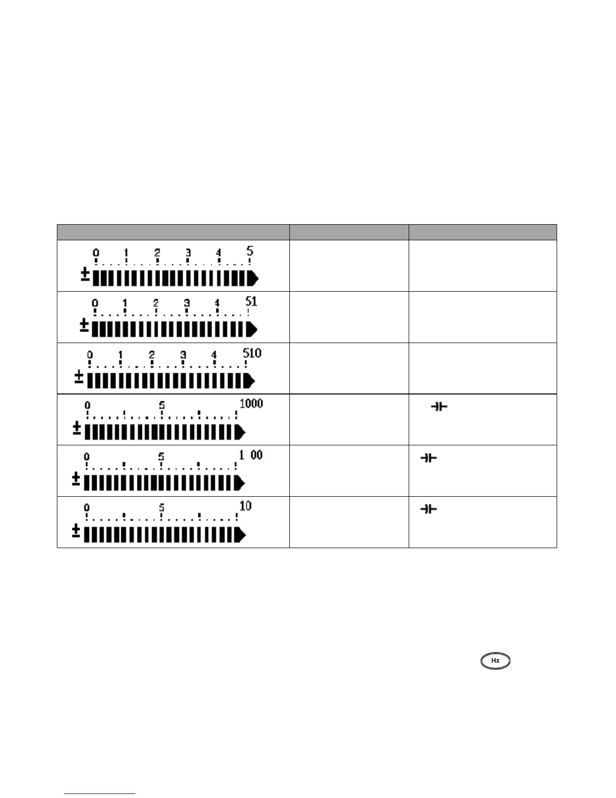
The “+” or “–” sign is indicated when the positive or
negative value has been measured or calculated. Each
segment represents 2500 or 500 counts depending on the
range indicated on the peak bar graph. See the table below.
Selecting display with the Hz button
The frequency measurement feature helps to detect the
presence of harmonic currents in neutral conductors and
determines whether these neutral currents are the result of
unbalanced phases or non- linear loads. Press to
access the frequency measurement mode for current or
voltage measurements — voltage or current on the secondary
Table 1-6 Analog bar range and counts
Range Counts/segments Used for the function
2500 V, Ω, Diode
2500 V, A, Ω
2500 V, A, Ω, nS
500
V,
500
500

 Loading...


