Home
Agilent Technologies
Multimeter
U3402A
Agilent Technologies U3402A User's And Service Guide
4
of 1
of 1 rating
129 pages
Give review
Manual
Specs
To Next Page
To Next Page
To Previous Page
To Previous Page
Loading...
Ope
rati
ons an
d Featu
res
2
U34
02A User
’s and Ser
vice Guid
e
31
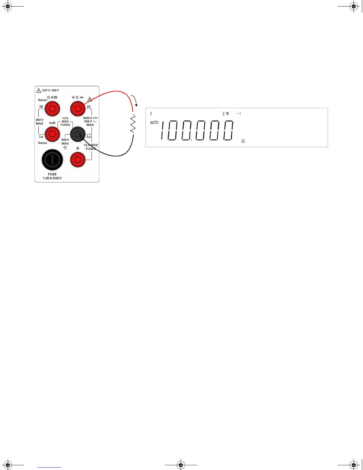
Figu
re 2-
10
2-wir
e/c
ontin
uity
t
est te
rmin
al
conn
ect
ion
and
dis
play
Resi
stan
ce
+
–
T
est cu
rrent
U3
402-
900
01.b
oo
k
Pag
e 31 F
riday
, Jul
y 24,
2009 4:
04 P
M
Downloaded from
Elcodis.com
electronic components distributor
50
52
Table of Contents
Safety Symbols
3
Regulatory Markings
4
General Safety Information
5
Environmental Conditions
7
In this Guide
11
Table of Contents
13
Getting Started
21
Introducing the Agilent U3402A Dual Display Multimeter
22
Initial Inspection
23
Standard Purchase Items
23
Original Packaging
24
Connecting Power to the Multimeter
25
Stacking the U3402A
26
Figure 1-1 Stacking the U3402A
26
Adjusting the Handle
27
Figure 1-2 Type of Handle Position
27
Figure 1-3 Attaching and Detaching the Handle
27
Product at a Glance
28
Product Dimensions
28
Figure 1-4 U3402A Dimensions
28
The Front Panel at a Glance
29
Figure 1-5 Front Panel
29
The Display at a Glance
30
Figure 1-6 VFD Full Display with All Segments Illuminated
30
Table 1-1 Display Annunciators
30
The Keypad a a Glance
32
Figure 1-7 Keypad
32
Table 1-2 Keypad Functions
32
The Terminal at a Glance
35
Figure 1-8 Input Terminal
35
Table 1-3 Input Terminal for Different Measurement Functions
36
The Rear Panel at a Glance
37
Figure 1-9 Rear Panel
37
Operations and Features
39
Making Measurements
40
Performing Voltage Measurements
41
Figure 2-1 ACV Terminal Connection and Display
41
Figure 2-2 DCV Terminal Connection and Display
42
Performing Current Measurements
43
Figure 2-3 ACI RMS or DCI (Ma) Terminal Connection and Display
43
Figure 2-4 ACI RMS or DCI (A) Terminal Connection and Display
44
Performing Frequency Measurements
45
Figure 2-5 Frequency Terminal Connection and Display
45
Performing Resistance Measurements
46
Figure 2-6 2-Wire Terminal Connection and Display
46
Performing Diode/Continuity Test
47
Figure 2-7 4-Wire Terminal Connection and Display
47
Figure 2-8 Forward-Biased Diode/Continuity Test Terminal Connection and Display
49
Figure 2-9 Reverse-Biased Diode/Continuity Terminal Connection and Display
49
Figure 2-10 2-Wire/Continuity Test Terminal Connection and Display
51
Selecting a Range
52
Table 2-1 Range Scale Value in Slow, Medium, and Fast Reading Rate
53
Setting the Reading Rate
54
Figure 2-11 Reading Rate Annunciator
54
Table 2-2 Reading Rates for Single Function Measurements
54
Selecting Secondary Display
56
Figure 2-12 Secondary Display
56
Table 2-3 Description for Dual Display Combination
57
Using the Setup Menu
58
Table 2-4 Setup Menu and Communication Parameters
58
Changing the Configurable Settings
59
Selecting Local Operation Mode
60
Operating Math Operations
61
Table 2-5 Math Operations for Different Measurement Functions
61
Dbm
62
Figure 2-13 Typical Dbm Operation Display
62
Rel
63
Figure 2-14 Typical Rel Operation Display
63
Minmax
64
Figure 2-15 Typical Max Operation Display
64
Figure 2-16 Typical Min Operation Display
65
Comp
66
Figure 2-17 Typical Comp Operation Display
66
Hold
67
Figure 2-18 Typical Hold Operation Display
67
Combination of Math Operations
68
Figure 2-19 Combined Math Operations Sequence
69
Table 2-6 Descriptions for Combined Math Operations
69
Measurement Tutorial
71
Applications for Using Dual Display
72
Table 3-1 Typical Combinations and Applications When Using Dual Display
72
Dual Display Operation Examples
73
Measure DC Voltage and AC Ripple on a Rectification Circuit
73
Figure 3-1 Terminal Connection When Measuring DC Voltage and AC Ripple on a Rectification Circuit
73
Measure AC and DC Current on a Rectification Circuit
74
Figure 3-2 Terminal Connection When Measuring AC and DC Current on a Rectification Circuit
74
Measure AC Voltage and Frequency on an AC Circuit
75
Measure DC Voltage and DC Current on a Transistor Circuit or Load
76
Measure Resistance Using 2-Wire Mode
78
Measure Resistance Using 4-Wire Mode
79
Measure True RMS AC+DC
80
Performance Test
81
Calibration Overview
82
Agilent Technologies Calibration Services
82
Calibration Interval
82
Recommended Test Equipment
83
Table 4-1 Recommended Test Equipments
83
Test Considerations
84
Input Connections
84
Performance Verification Test Overview
85
Performance Verification Test
85
DC Voltage Verification Test
85
Table 4-2 DC Voltage Verification Test
86
DC Current Verification Test
87
Table 4-3 DC Current Verification Test
87
Resistance Verification Test
88
Table 4-4 2-Wire Verification Test
88
Diode Verification Test
91
Frequency Verification Test
91
Table 4-6 Diode Verification Test
91
Table 4-7 Frequency Verification Test
91
AC Voltage Verification Test
92
Table 4-8 AC Volts Verification Test
92
AC Current Verification Test
93
Table 4-9 AC Current Verification Test
93
Disassembly and Repair
95
Operating Checklist
96
Types of Service Available
97
Cleaning
98
Repackaging for Shipment
98
To Replace the Power Line Fuse
99
Table 5-1 Type of Supplied Fuse (According to Country of Destination)
99
To Replace a Current Input Fuse
100
Electrostatic Discharge (ESD) Precautions
100
Mechanical Disassembly
101
Replaceable Parts
107
Table 5-2 Replaceable Parts
107
Rack Mounting
108
Specifications and Characteristics
109
General Characteristics
110
Measurement Category
112
Measurement Category Definitions
112
Specifications
113
DC Voltage
113
Table 6-1 DCV Resolution, Full Scale Reading, and Accuracy
113
DC Current
114
Table 6-2 DCI Resolution, Full Scale Reading, and Accuracy [±(% of Reading + Count)]
114
AC Voltage (True RMS, AC Coupling Mode)
115
Table 6-3 ACV Resolution, Full Scale Reading, and Accuracy [±(% of Reading + Count)]
115
AC Voltage (True RMS, AC+DC Coupling Mode)
116
Table 6-4 Acvac+DC Resolution, Full Scale Reading, and Accuracy [± (% of Reading + Count)]
116
AC Current (True RMS, AC Coupling Mode)
117
Table 6-5 ACI Resolution, Full Scale Reading, Burden Voltage, and Accuracy [± (% of Reading + Count)]
117
AC Current (True RMS, AC+DC Coupling Mode)
118
Table 6-6 Aciac+DC Resolution, Full Scale Reading, Burden Voltage, and Accuracy [± (% of Reading + Count)]
118
Resistance
119
Diode Test/Continuity
120
Resistance/Continuity (2-Wire)
120
Frequency
120
Decibel (Db) Calculation
121
Supplemental Specifications
122
Display Counts
122
Measurement Specifications
122
To Calculate Total Measurement Error
127
Accuracy Specifications
128
Transfer Accuracy
128
Other manuals for Agilent Technologies U3402A
User's Guide And Service Guide
127 pages
Quick Start Guide
61 pages
4
Based on 1 rating
Ask a question
Give review
Questions and Answers:
Need help?
Do you have a question about the Agilent Technologies U3402A and is the answer not in the manual?
Ask a question
Agilent Technologies U3402A Specifications
General
Brand
Agilent Technologies
Model
U3402A
Category
Multimeter
Language
English
Related product manuals
Agilent Technologies U3606A
288 pages
Agilent Technologies U1252B
191 pages
Agilent Technologies U1241B
89 pages
Agilent Technologies U1253B
225 pages
Agilent Technologies U1242B
89 pages
Agilent Technologies U1242A
85 pages
Agilent Technologies U1241A
85 pages
Agilent Technologies U1231A
133 pages
Agilent Technologies U1251A
169 pages
Agilent Technologies 3458A
372 pages
Agilent Technologies 34401A
242 pages
Agilent Technologies 34410A
144 pages

 Loading...


