Performance Test 4
U3402A User’s and Service Guide 67
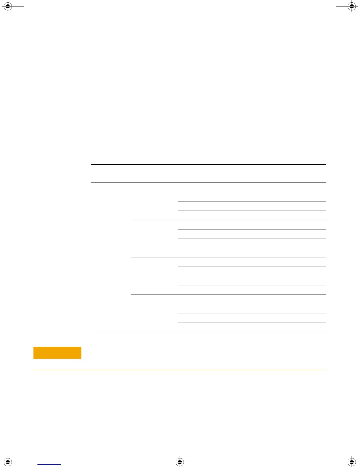
DC Current Verification Test
1 Connect the calibrator to the front panel Hi and Lo input connectors.
2 Select each function and range in the order shown in Table 4- 3. Provide the
input shown in Table 4- 3.
3 Make a measurement and observe the result. Compare measurement results
to the appropriate test limits shown in Table 4- 3. (Be certain to allow for
appropriate source settling when using the Fluke 5520A.)
Ta b l e 4- 3 DC current verification test
Function Reading rate Input Range Error from nominal
one year
DC current
Slow
0.0000 mA 12 mA ±1.5 µA
0.000 mA 120 mA ±5 µA
0.00 mA 1200 mA ±50 µA
0.0000 A 12 A ±0.5 mA
Medium
0.000 mA 40 mA ±6 µA
0.00 mA 120 mA ±30 µA
0.0 mA 1200 mA ±0.3 mA
0.000 A 12 A ±3 mA
Slow
10.0000 mA 12 mA ±6.5 µA
100.000 mA 120 mA ±55 µA
1000.00 mA 1200 mA ±1.55 mA
10.0000 A 12 A ±20.5 mA
Medium
36.000 mA 40 mA ±42 µA
100.00 mA 120 mA ±0.13 mA
1000.0 mA 1200 mA ±1.8 mA
10.000 A 12 A ±23 mA
Connect calibrator to multimeter’s A and Lo terminals before applying 10 A.
U3402-90001.book Page 67 Friday, July 24, 2009 4:04 PM
Downloaded from Elcodis.com electronic components distributor

 Loading...


