16 PowerFlex® 700S Drives - Phase I Control (Frame Sizes 9 & 10)
Floor and Wall Mounting for Frame 10 Size Drives
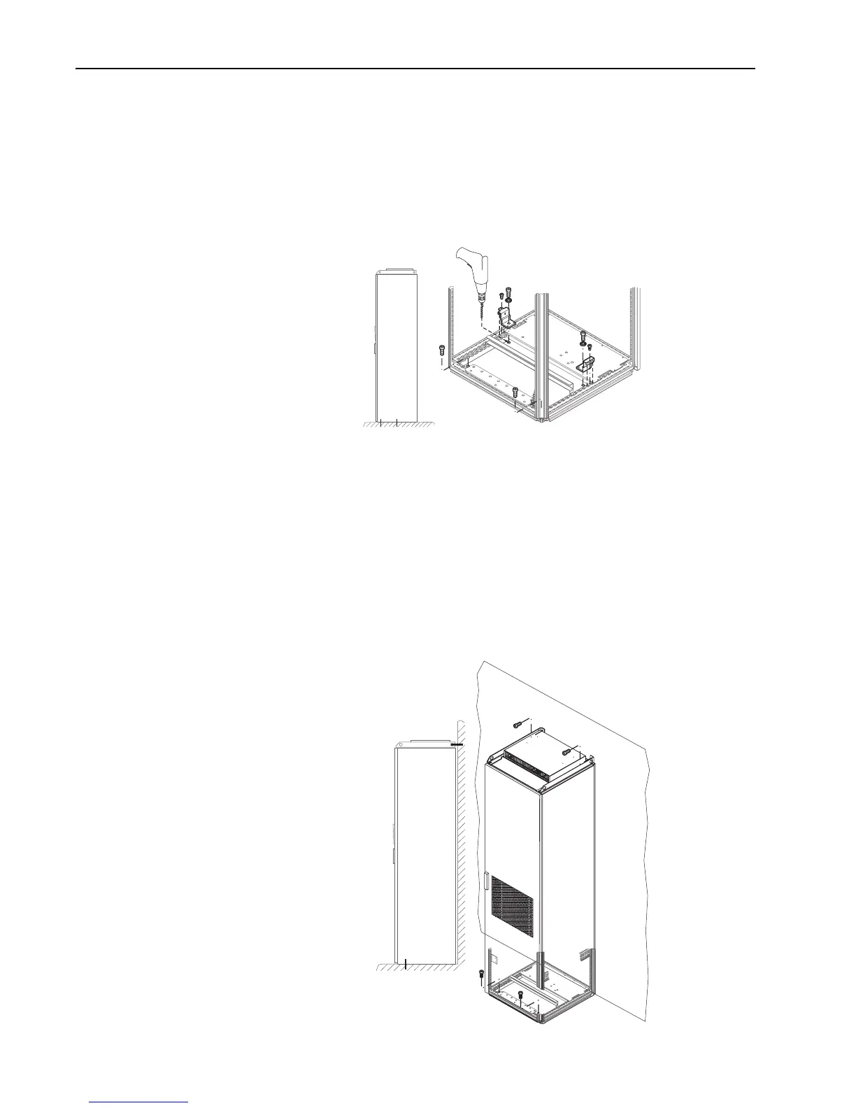
Floor Only Mounting
Secure drive to the floor with anchor bolts in the front corner holes of the enclosure
base plate. Additionally secure the drive using the mounting plates as needed (Rittal
part no. 8800-210 or equivalent). Do this as close to the choke assembly plate as
possible. With this method the holes through base plate must be drilled on-site.
Wall Mounting
Secure drive to the floor with anchor bolts in the front corner holes of the enclosure
base plate. Secure the drive by bolting the adjustable lifting rails to the rear wall or
supporting structure.
Important: If it is important to align the drive cabinet vertically with adjacent
Rittal cabinets, you may need to place shims under the drive cabinet
or use leveling feet throughout the cabinet line-up. The
Allen-Bradley factory may have removed the standard plastic plugs
from the bottom of the cabinet when installing the shipping feet.
This reduces the height of the cabinet by 2 mm.
wall

 Loading...


